Call Us Now! KnownPCB +86 755 2794 4155 KnownPCB sales@knownpcb.com
Shenzhen KNOWNPCB Technology Co., Ltd.
KnownPCBEN KnownPCBCN
KnownPCB
KnownPCB
About Us About Us

About Us

Home > 
  • About Us
  • >
  • News
  • How LED light work? Learn more about LED board

    How LED light work? Learn more about LED board

    Have you noticed that now more and more of our lighting is using led lighting.What is LED? Compared to the traditional light bulbs, LEDs have lower power consumption, longer lifetime and higher energy efficiency. In the PCB industry,when we say LED PCB, it refers to the pcb used for LED lighting, if you are looking for a suitable LED PCB for your lighting system, this article may bring you something. WHAT ARE LEDS COMPOSED OF?LED is an initial light-emitting diode that produces light when an electric current passes through. LEDs typically have negative and positive electrodes, which generate light in the visible light region.The LEDS are glued to the PCB by soldering process and have electrical connections for lighting.Since light-emitting diodes dissipate a lot of heat when they are in use, when you are designing LED, the metal core is usually the best choice for LED PCB, it is because that it dissipates heat more faster. Among them, the metal material aluminum is the most widely used

    Know Detail

    PCB Assembly for Industrial Robot.Flexible circuit board price composition

    PCB Assembly for Industrial Robot.Flexible circuit board price composition

    Apr 22,2024

        First, the different materials used in flexible circuit boards cause the diversity of prices  Taking ordinary double panels as an example, the board material is generally PET, PI, etc., the board thickness ranges from 0.0125mm to 0.10mm, and the copper thickness ranges from 0.0125mm to 0.10mm. Oz to 3 Oz, all of which creates a huge price difference in sheet metal alone; The different brands of materials also have a certain price difference, so the different materials cause the diversity of prices.  Second, the different production processes used in flexible circuit boards cause the diversity of prices  Different production processes result in different costs. Such as gold-plated plate and tinned plate, the accuracy of the production shape, the use of silk screen lines and dry film lines will form different costs, leading to the diversity of prices.  Third, the price diversity caused by the different difficulty of the flexible circuit board itself  Even if the material is the same

    Know Detail

    The use of pad and via

    The use of pad and via

    Apr 20,2024

        For some customers, pcb sampling production design is seriously non-standard, it is impossible to distinguish which is pad and which is via usage, sometimes conductive holes are processed with pad, sometimes key holes are processed with via, the design is confused, resulting in increased errors, according to incomplete statistics of Jialicom, the problems caused by non-standard design account for more than 50% of customer complaints. And for the current situation of the circuit board, some of the processing of Philin engineers, because the customer design documents are not standardized, and make mistakes, help customers modify the document, the non-standard design, with their own experience to deal with engineering data, which leads to and contributes to the customer's design is not standardized, Jialicang once again stated that the last time you do the right, does not mean that your file is right! All engineers must pay attention to the design standards and specifications! Jialich

    Know Detail

    PCB proofing development

    PCB proofing development

    Apr 19,2024

        An ordinary pcb board proofing production line needs more than 20 million yuan, multi-layer boards need to invest 50 million yuan, and HDI needs to invest more than 200 million yuan. Due to the huge industry, the division of labor is very fine, there are single-station process outsourcing specializing in drilling, etc., and low-grade products are oversupplied.  HDI and other high-end printed circuit board industry is a capital, labor-intensive industry, management and technical requirements are relatively high, often become the bottleneck of capacity expansion.  Glass fiber yarn: glass fiber yarn processing by silica sand and other raw materials in the kiln calcined into liquid, through the PCB through the very small alloy nozzle to draw very fine glass fiber, and then hundreds of glass fiber twisted into glass fiber yarn. Kiln construction investment is huge, for the capital intensive industry, 30,000 tons of kiln needs 400 million yuan, the new kiln needs 18 months, the business

    Know Detail

    PCB Assembly for Medical Equipment.Dry film mask with perforation

    PCB Assembly for Medical Equipment.Dry film mask with perforation

    Apr 18,2024

        Many customers believe that after a hole is broken, the film temperature and pressure should be increased to enhance its adhesion. However, this view is not correct because the solvent in the corrosion resistant layer evaporates excessively when the temperature and pressure are too high, making the dry film brittle and thin. During development, it is very easy to break the hole. We always need to maintain the toughness of the dry film. Therefore, after a hole is broken, we can improve it from the following points:  1. Reduce film temperature and pressure  2. Improve drilling edge  3. Increase exposure energy  4. Reduce development pressure  5. After applying the film, the parking time should not be too long to avoid causing the semi fluid like drug film at the corner to diffuse and thin under pressure  6. During the film application process, do not tension the dry film too tightly

    Know Detail

    PCB copper treatment experience

    PCB copper treatment experience

    Apr 17,2024

        Copper coating, that is, the idle space on the PCB is used as the base level, and then filled with solid copper, these copper areas are also called copper filling. The significance of copper coating is to reduce the ground impedance and improve the anti-interference ability. Reduce voltage drop, improve power efficiency; Also, connect to the ground wire to reduce the area of the loop. If there are many PCB places, such as SGND, AGND, GND, etc., how to cover copper? My approach is that according to the different positions of the PCB board, the most important "ground" is used as a benchmark reference to independently cover copper, and digital and analog copper are separated from each other. At the same time, before coating copper, first bold the corresponding power cable: V5.0V, V3.6V, V3.3V(SD card power supply), and so on. In this way, multiple deformation structures of different shapes are formed.  The copper coating needs to deal with several problems: one is the single point con

    Know Detail

    Driver Circuit Board High Frequency.PCB high speed board wiring experience of more than 4 layers

    Driver Circuit Board High Frequency.PCB high speed board wiring experience of more than 4 layers

    Apr 16,2024

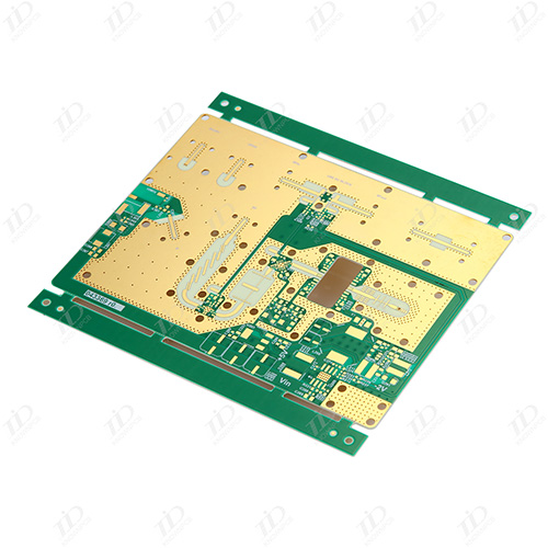
        1, 3 points above the line, try to make the line through each point, easy to test, the line length as short as possible.  2, try not to put wires between pins, especially between and around integrated circuit pins.  3, the lines between different layers should not be parallel as far as possible, so as not to form an actual capacitor.  4, the wiring is as straight as possible, or 45 degree line, to avoid electromagnetic radiation.  5, ground wire, power cord at least 10-15mil above (for logic circuit).  6. Try to connect the ground polysemy lines together and increase the ground area. Line to line as neatly as possible.  7, pay attention to the uniform emission of components, so as to install, plug-in, welding operation. The text is discharged in the current character layer, the position is reasonable, pay attention to the orientation, avoid being blocked, easy to produce.

    Know Detail

    Electromagnetic compatibility design of mobile phone PCB

    Electromagnetic compatibility design of mobile phone PCB

    Apr 13,2024

        1, choose a reasonable wire width  Since the impact interference caused by the transient current on the printed line is mainly caused by the inductive component of the printed wire, the inductance of the printed wire should be minimized. The inductance of the printed wire is proportional to its length and inversely proportional to its width, so a short and fine wire is advantageous for suppressing interference. Signal lines for clock leads, line drivers, or bus drivers often carry large transient currents, and printed wires should be as short as possible. For discrete component circuits, when the width of the printed wire is about 1.5mm, the requirements can be fully met; For integrated circuits, the printed wire width can be selected between 0.2 and 1.0mm.  2, use the correct wiring strategy  The use of equal wiring can reduce the inductance of the wire, but the mutual inductance and distributed capacitance between the wires increase, if the layout allows, it is best to use a well

    Know Detail

    pcb assembly manufacturer.Ultra-comprehensive pcb failure analysis technology

    pcb assembly manufacturer.Ultra-comprehensive pcb failure analysis technology

    Apr 12,2024

        As the carrier of various components and the hub of circuit signal transmission, PCB has become the most important and critical part of electronic information products, and its quality and reliability level determine the quality and reliability of the whole equipment. With the miniaturization of electronic information products and the environmental requirements of lead-free and halogen-free, PCB has also developed in the direction of high density, high Tg and environmental protection. However, due to cost and technical reasons, PCB has a large number of failure problems in the production and application process, and therefore caused a lot of quality disputes. In order to find out the cause of the failure in order to find a solution to the problem and distinguish the responsibility, it is necessary to carry out failure analysis on the failure cases.  To obtain the exact cause or mechanism of PCB failure or failure, it is necessary to follow the basic principles and analysis process,

    Know Detail
  • <
  • 1
  • 2
  • 3
  • 4
  • 5
  • 6
  • >
  • 最后一页
  • ogo

    Appointment Experience

    X