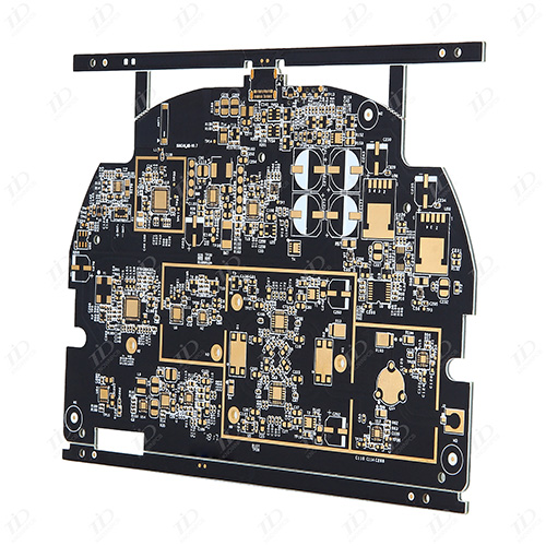
Generally speaking, the four -layer circuit board can be divided into top,
bottom, and two middle layers. On the top and the bottom layer, the middle layer
first uses Add Plane to add internal Plane1 and Internet Plane2 to the most
power layer such as VCC and stratum (that is, the corresponding network labels
are connected to the corresponding network label with ADD Plane Do not use Add
Layer, this will increase the Midplayer, which is mainly used as a multi -layer
signal line placement), so that Plnne1 and Plane2 are two layers of copper
leather connected to the power VCC and ground GND. If there are multiple power
supplies such as VCC2 or strata such as GND2, first use a thick wire or fill the
Fill in Plane1 or Plane2 (at this time the bronze skin corresponding to the
corresponding copper or the corresponding of Fill does not exist. You can
clearly see the wire or obviously see the wire or you can clearly see the wire
or the light or the light or Fill) The rough area of the power supply or land
(mainly for the convenience of the Place/Split Plane command in the back), and
then use the Place/Split Plane in the corresponding area of InternaL Plane1 and
Internet Plane2 (ie VCC2 copper leather and the VCC2 bronze skin and GND2 copper
sheet, there is no VCC in the same Plane) (note that different network surface
layers in the same Plane should not overlap in the same Plane. Set Split1 and
Split2 in the same PLANE two, and Split2 is inside Split1. The version of the
version is made. It will automatically separate the two pieces according to the
border of Split2 (Split1 is distributed in the periphery of Split). Just pay
attention to the pads or perforated pads of the same network table as Split1
when overlap. question). At this time, the over -perforations on the area are
automatically connected to the copper skin corresponding to the layer. The
device pins of the DIP packaging device and the connection plug -in through the
upper and lower panels will automatically open with the PLANE in the area. Click
Design/Split Planes to view each Split Planes
Read recommendations:
10L 8.0mm thick board
2L special-shaped board
14L ENIG PCB
smt electronics assembly manufacturer
Copper PCB Manufacturing Manufacturing
 +86 755 2794 4155
  sales@knownpcb.com
 EN
EN CN
CN
 Home >


