Call Us Now! KnownPCB +86 755 2794 4155 KnownPCB sales@knownpcb.com
Shenzhen KNOWNPCB Technology Co., Ltd.
KnownPCBEN KnownPCBCN
KnownPCB
KnownPCB
About Us About Us

About Us

Home > 
  • About Us
  • >
  • News
  • How LED light work? Learn more about LED board

    How LED light work? Learn more about LED board

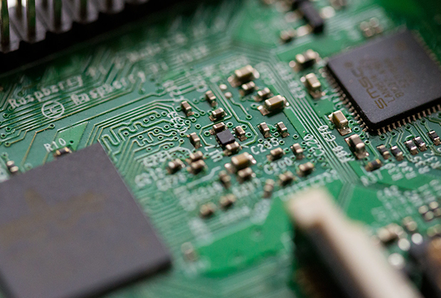
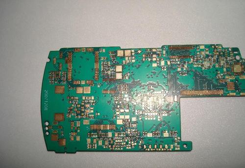
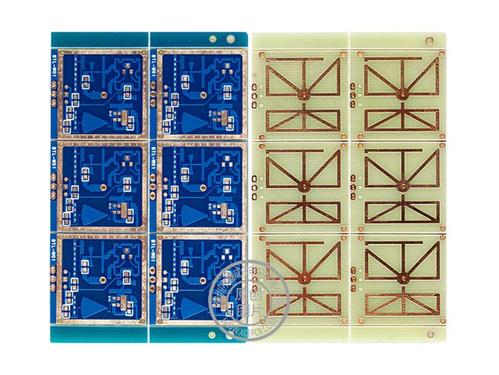
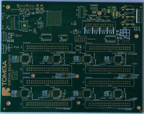
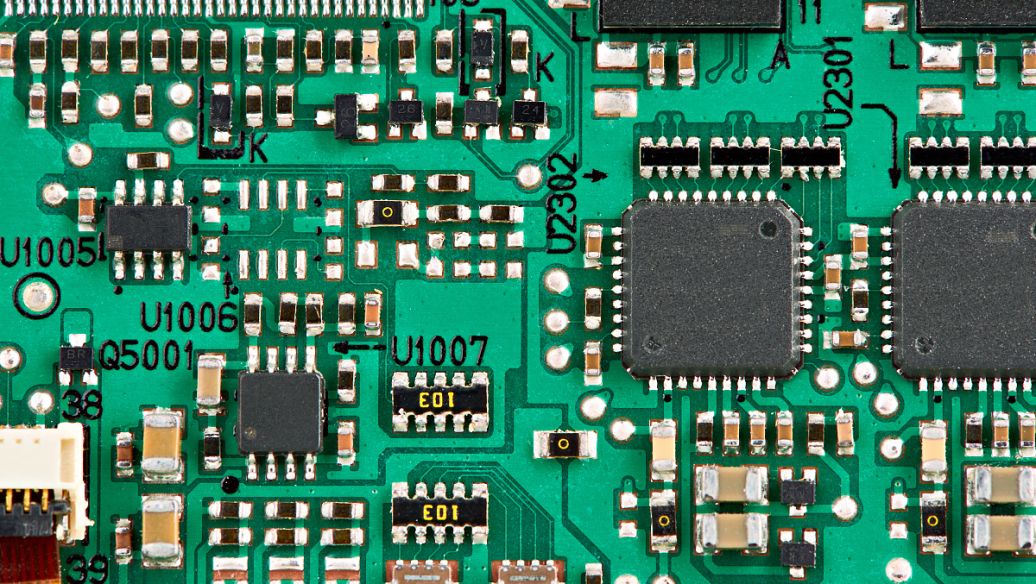
    Have you noticed that now more and more of our lighting is using led lighting.What is LED? Compared to the traditional light bulbs, LEDs have lower power consumption, longer lifetime and higher energy efficiency. In the PCB industry,when we say LED PCB, it refers to the pcb used for LED lighting, if you are looking for a suitable LED PCB for your lighting system, this article may bring you something. WHAT ARE LEDS COMPOSED OF?LED is an initial light-emitting diode that produces light when an electric current passes through. LEDs typically have negative and positive electrodes, which generate light in the visible light region.The LEDS are glued to the PCB by soldering process and have electrical connections for lighting.Since light-emitting diodes dissipate a lot of heat when they are in use, when you are designing LED, the metal core is usually the best choice for LED PCB, it is because that it dissipates heat more faster. Among them, the metal material aluminum is the most widely used

    Know Detail

    PCB's circuit characteristics

    PCB's circuit characteristics

    May 26,2023

        Each trace line is composed of the flat narrow parts of the residual on -carved copper foil. The resistance determined by its width, thickness, and length must be low enough to be carried by the conductor carrier. Power and ground wiring may need to be wider than signal wiring. In the multi -layer board, the entire layer can be mainly solid copper, for ground planes for shielding and power returned. For microwave circuits, transmission cables can be arranged in a plane, such as band lines or micro bands, and their size is carefully controlled to ensure consistent impedance. In radio frequency and fast -switch circuits, the inductance and capacitors of the printing circuit board conductor become an important circuit component, which is usually unwilling; on the contrary, they can be regarded as a conscious part of the circuit design without additional separate components.

    Know Detail

    PCB surface installation technology

    PCB surface installation technology

    May 26,2023

        Surface installation technology appeared in the 1960s, developed a development momentum in the early 1980s, and was widely used in the mid -1990s. Recetishment of the component to make it have a small metal piece or end cover that can directly weld on the PCB surface, rather than the wire through the hole. The component becomes smaller, and the components on both sides of the circuit board are more common than the installation of the hole, allowing smaller PCB components to have higher circuit density. The surface installation is very suitable for highly automation, reducing labor costs and greatly increasing productivity. The components can be installed on the load. The size and weight of the surface installation element can be one -quarter to one -tenth of the hole components, and the passive component is much cheaper. However, the price of semiconductor surface installation devices (SMD) depends more on the chip itself rather than packaging. Compared with larger packaging, there

    Know Detail

    PCB copy of the contact system reliability design

    PCB copy of the contact system reliability design

    May 25,2023

      Correctly selecting the contact material can improve the reliability and life of relay IRF520NPBF. Different relays are different due to the different nature and disconnection capacity of the contact load, and the types and degrees of wear of the contacts are also different; these factors must be taken into account when the design uses contacts and reed materials. The selected contacts and reed materials should meet the following basic requirements:  ① It has good conductivity and thermal conductivity.  ② The contact and plating material should be resistant to arcs or electrical spark wear and mechanical wear, and have a certain hardness and anti -adhesion performance.  ③ The reed material should have good elasticity.  2) Requirements for the design and size design of the contact contact:  ① For small and small loads such as micro -micro, ultra -small, the contacts should be in contact with point contact. PCB copies to increase the pressure on the contact site and destroy pollutants

    Know Detail

    PCB copy value

    PCB copy value

    May 25,2023

        Some people have made such assumptions: If the laptop research takes two years, after studying abroad, we will start to enter research for two years, then in the past two years, we can only sell foreign notebooks. In this way, not only our own laptops are two years later than foreign countries, but in the past two years, the market share and brand effects of foreign laptops in China have reached an indestructible level.  However, if we adopt reverse technology research such as PCB copy board, at the beginning of the laptop, we can quickly keep up with new products research, and we can also add new functions to it for new breakthroughs. In this way, we can be in With its own technological achievements in a short time to compete with foreign monopoly products and quickly surpass.  Specifically, the value of PCB copy is reflected in the following aspects:  From the perspective of an enterprise  Callen can help enterprises quickly update their replacement and keep up with the latest tr

    Know Detail

    Reverse push of PCB schematic diagram

    Reverse push of PCB schematic diagram

    May 25,2023

        The principle diagram is a drawing composed of electrical symbols to analyze the principle of circuit. It has an indispensable role in product debugging, maintenance, and improvement. Principle diagram reversing and positive design is the opposite. The positive design is first designated by the principle diagram, and then the PCB design is performed according to the schematic diagram. The schematic diagram is convenient to analyze the product and assist the later product prototype to debug production or improve the upgrade.  In the process of product reverse technology research and imitation development, the production of the BOM list and the position diagram of the patch, the production of the coordinates of the component of the SMT patch machine are all later model welding, patch processing, and complete prototype design and assembly production. Link.  BOM (Material List) is the basis for the purchase of device materials, which records the various components, modules and other sp

    Know Detail

    PCB design

    PCB design

    May 25,2023

        In high -speed design, the characteristic impedance of controllable impedance boards and lines is one of the most important and common problems. First understand the definition of the transmission line: the transmission line consists of two conductors with a certain length, one is used to send a signal, and the other is used to receive signals (remember the concept of "loop" instead of "ground"). In a multi -layer board, each line is part of the transmission line, and the adjacent reference plane can be used as the second line or loop. The key to a "good performance" transmission line is to keep its characteristic impedance constant in the entire line.  The key to the "controllable impedance board" is to make the characteristic impedance of all lines satisfy a prescribed value, usually between 25 ohms and 70 ohms. In the multi -layer circuit board, the key to the good transmission line performance is to keep its characteristic impedance constant in the entire line.  But what exactl

    Know Detail

    PCB board can be tested design points introduction

    PCB board can be tested design points introduction

    May 24,2023

        The testability design of a good product can simplify the preparation of inspection and product final testing in the production process, improve test efficiency, reduce test costs, and easily find the product defects and faults, thereby ensuring the quality stability and reliable quality of the product. sex.  1. Testability of PCB design  Like the manufacturing design of PCB, the testability design of PCB also belongs to the processing design of the printed board, which also includes the testability of the printed board manufacturing and finished printing board (light board) Two parts of testability, the test methods and requirements of these two parts are completely different. For the designer of PCB, it is necessary to understand both the performance and testing methods that need to be tested on the printed board, and to understand the installation test requirements and test methods of the printed board assembly parts.  With the miniaturization of electronic products, the online

    Know Detail

    Six -layer boards overlap

    Six -layer boards overlap

    May 24,2023

        For the design of the chip density and the high clock frequency, the design of the 6 -layer board should be considered. It is recommended to stack the layer:  1. Sig -GND -SIG -PWR -GND -SIG; For this scheme, this superposition layer scheme can get better signal integrity. The impedance of the wiring layer can be better controlled, and both floors can well absorb magnetic lines. And in the case of power and strata, it can provide a good return path for each signal layer.  2. GND -SIG -GND -PWR -SIG -GND; For this solution, this plan is only applicable to the situation where the density density is not very high. This layer has all the advantages of the above layer, and this top and bottom layer The horizon is relatively complete and can be used as a better shield. It should be noted that the power layer should be close to the non -main component surface, because the plane of the bottom layer will be more complete. Therefore, EMI performance is better than the first solution.  Summar

    Know Detail
  • 第一页
  • <
  • 80
  • 81
  • 82
  • 83
  • 84
  • 85
  • 86
  • 87
  • 88
  • >
  • 最后一页
  • ogo

    Appointment Experience

    X