Heavy Copper PCB Supplier for Power Electronics
Energy & Power Electronics Push PCB Design Into Extreme Constraints. They are constraints emerging from high-power, high-density energy systems operating at the edge of electrical and thermal limits.
| | ||||||||
Real Power-Electronic Products Create Distinct PCB Challenges—Heat, High Voltage, EMI, and Mechanical Stress.
Different power-electronic applications combine high current, thermal density, isolation requirements, and switching-noise constraints in different ways.
Each scenario below maps real product needs to PCB constraints.
Learn How We Solve Your Design Challenges
Application Scenario | Design Challenges / Functional Needs | Required PCB Capabilities (Industry-Specific) |
High-Power Conversion (AC/DC, DC/DC) | - High thermal load from switching devices | - Heavy-copper (2–6 oz) multilayers |
| - Wide input/output voltage stress | - Thermal-via arrays under MOSFETs/IGBTs | |
| - Creepage/clearance requirements | - Insulation-strength materials (FR-4, FR-5, PI, polyimide) | |
- Switching-edge EMI/EMC risk | - Controlled creepage/clearance spacing | |
Battery Management Systems (BMS) | - HV distribution + sensor isolation | - High-isolation stackups |
| - Accurate sensing for cell balancing | - Carefully balanced copper distribution | |
| - Large copper areas for discharge currents | - Reinforced spacing for HV/EV compliance | |
- HV transient protection | - Low-drift sensor routing | |
Motor Control / Inverters | - High current loops | - Heavy-copper layers for current loops |
| - Fast switching generating EMI | - EMI-aware power stage isolation | |
| - Mixed-signal + power stage on same board | - Reinforced mechanical reliability | |
- High vibration / thermal cycling | - Thermal-optimized copper planes | |
Fast Chargers / PD Power Stages | - High density in compact form factors | - Ultra-efficient thermal-path design |
| - Thermal hotspots | - Low-inductance power loops | |
| - HV + HF switching | - High-voltage creepage strategies | |
- Strict EMI limits | - Specialized laminates for heat spreading |
Power-electronics stackups are driven by current density, thermal load, high-voltage isolation, and the fast-switching behavior of GaN/SiC devices.
The materials and layer structures below reflect the constraints that determine long-term reliability—not optional enhancements.
 | Power-grade stackups must consider:
These are not “capabilities”—they are the industry constraints that shape reliable power-electronics PCBs. Upload Files |
Request a Free Design Consultation
The exact engineering checks we perform for each project/design/application include:
|
|
|
|---|---|---|
| Thermal hotspots under MOSFETs / SiC / GaN devices | Copper thickness, thermal-via patterning, heat-spreading paths | Prevents device overheating & early failure |
| High-current loop inefficiency | Current path geometry, loop inductance, copper distribution | Reduces switching loss & EMI noise |
| Creepage / clearance violations | HV spacing rules, contamination risk, insulation materials | Prevents arcing & compliance failures |
| EMI coupling between power & control circuits | Switching edges, return-path noise, isolation zones | Stabilizes sensing accuracy and reduces noise |
| Copper cracking under thermal cycling | Via reinforcement, copper balance, mechanical stress zones | Improves long-term reliability |
| Imprecise sense-line routing | Sensor-trace placement, Kelvin connection strategy | Improves BMS accuracy & cell balancing performance |
| Transient spikes during HV switching | Ground strategy, snubber network PCB layout | Reduces stress on MOSFETs/SiC modules |
|
|
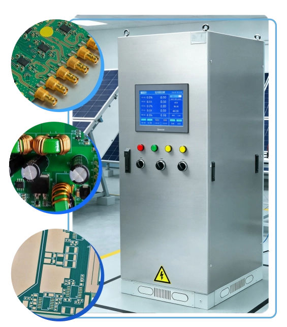
 |  |
Proven by 7 industries, 4000+ customer projects
Please contact us at sales@knownpcb.com, ask for engineering support here or use the form below to reach out to KnownPCB | Get In Touch Today |


 WHAT WE SOLVE
 WHAT WE CHECK
 WHY IT MATTERS
 Reinforced high-current connector interfaces and anchor pads, which reduces intermittent opens in chargers/OBCs
 A heavy-copper stack-up that stayed flat after reflow—preventing assembly misalignment and yield loss in power boards
 Moved heat out from shunts and inductors with smarter plane distribution, therefore current sensing stays stable at high duty
 Tamed switching-noise coupling into control circuits by tightening loops and returns, improving EMC results in real installations
 Cleaner references for gate-drive and feedback routing helped avoid false triggering, so power stages switch predictably
 Added HV keepouts/slots to meet creepage & clearance and cut PD risk, preventing insulation breakdown in energy storage systems