
Get A Quote
CN
PCB Product Capabilities

From FR4,high TG,Polyimide to high-power, RF, and specialized materials — explore all PCB product categories including HDI and rigid-flex for modern hardware. |
 |

HDI PCB |

Rigid-Flex PCB |

Multilayer PCB |

High-Power |
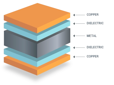
Metal Core PCB |

High-Speed |

Flexible PCB |
|
| Lead Time |
|
|
|
5-15 Days | 5-15 Days | 5-15 Days | 5-10 Days |
| Layer Count | 4–12 Layers |
Rigid: 2–10 Layers Flex: 1–4 Layers |
4-32 Layers | 2–10 Layers | 2–8 Layers | 4–20 Layers | 1-4 Layers |
| Supported Materials | FR-4 high-Tg / low-Dk laminates | Polyimide / FR-4 / adhesive-less PI | FR-4 / high-Tg FR-4 | FR-4 / high-Tg FR-4 | Copper Core / Aluminum Core / FR-4 | Megtron 6/7, Tachyon, TU-872, low-Dk/Df FR-4 | Polyimide / adhesive-less PI |
| Typical Applications | IoT / Wearables / Smartphones / Compact Modules | AR/VR / Foldable Devices / Medical Wearables | Industrial / Automation / Consumer Electronics | Power Electronics / Chargers / Motor Control | LED Lighting / DC-DC Converters / Power Control / Thermal Boards | 5G / Servers / Telecom Equipment | Wearables / Cameras / Connectors / Sensors |
| Key Features |
◎ 2-3 levels microvia ◎ Fine-pitch BGA fan-out ◎ Impedance control |
◎ Dynamic bending ◎ Stable interconnects ◎ Weight reduction |
◎ Cost-effective ◎ Stable performance ◎ Widely applicable |
◎ High current carrying ◎ Thermal via arrays ◎ HV spacing |
◎ Efficient heat dissipation ◎ High thermal conductivity ◎ Stable mechanical structure |
◎ 10–112G SerDes ◎ Low skew ◎ Backdrill support |
◎ Ultra-thin ◎ Small bending radius ◎ Dynamic flex |
|
|
Learn More | Learn More | Learn More | Learn More | Learn More | Learn More | Learn More |
The comparison above describes standard configurations. Higher-layer counts and special material or copper requirements are reviewed against your stackup, quantity and manufacturing files. Lead times are confirmed after engineering review and material availability checks.
They help engineers quickly evaluate manufacturability and match real PCB performance with high-speed or high-power design requirements.

| Product Type | Min Trace/Space | Min Drill / Microvia | Aspect Ratio | Max Layers | Board Size Max | HDI Levels | Blind/Buried Via | Via Filling | Backdrill |
| HDI PCB | 🔵 2/2 mil |
🔵 0.075–0.1 mm laser via |
1:1 (microvia) / 1:10 (TH) |
🔵 12–16L | 🔵 250×310 mm | 1–3 levels | Yes | resin / copper-filled | Yes |
| Rigid-Flex PCB | 🔵 3/3 mil | 0.1 mm laser | 1:1–1:12 | 🔵 10L | 🔵 350×600 mm | 1 level | No (usually) | No | No |
RF / Microwave PCB
High-Speed /
Low-Loss PCB
4/4 mil
mechanical only
1:08
2–8L
🔵 400×500 mm
–
No
No
No
🔵 3/3 mil
laser optional
1:10
4–20L
🔵 300×500 mm
1–2 levels
Yes
resin
Yes
Heavy-Copper PCB
6/6 mil (2 oz)
mechanical only
1:08
2–10L
🔵 350×450 mm
–
No
No
No
8/8 mil (4–6 oz)
Multilayer PCB
🔵 3/3 mil
mechanical
1:10
🔵 4–32L
🔵 450×600 mm
–
Optional
No
Optional
FPC (Flex PCB)
3/3 mil
0.1 mm laser
1:1–1:10
1–4L
🔵 300×500 mm
–
No
No
No
| Product | Supported Material Systems | Tg Range | Low-Loss Options | Special Requirements |
| HDI | FR-4 high-Tg, S1000H | 150–170°C | – | thin cores (50–75 µm) |
| Rigid-Flex |
PI (adhesive / non-adhesive) FR-4 |
150–200°C | – | bend radius validation |
| RF PCB |
Rogers 4003/4350B/ PTFE,/hydrocarbon |
120–200°C | Yes | Dk/Df stability |
| High-Speed PCB | Megtron 6/7, Tachyon, IT-88 | 180–200°C | Yes | low roughness foil |
| Heavy-Copper | FR-4 / FR-5 | 130–170°C | – | thick copper lamination |
| Multilayer PCB | FR-4 / FR-5 | 130–150°C | – | high aspect ratio control |
| FPC | Polyimide | 200–260°C | – | flex reliability |
| Factors | HDI PCB | Rigid-Flex | RF PCB | High-Speed PCB | Heavy-Copper PCB | Multilayer PCB | FPC |
| Thermal Cycling | good | excellent | medium | good | good | good | medium |
| Vibration Resistance | good | good | medium | good | excellent | good | low |
| Flex/Bend Life | – | excellent | – | – | – | – | excellent |
| Via Reliability | high | medium | medium | high (backdrill optional) | high | medium | – |
| Max Copper Weight | 1 oz | 1 oz rigid / 0.5 oz flex | 1 oz | 1 oz | 🔵 2–6 oz | 1–2 oz | 0.5–1 oz |
| Thermal Via Support | Yes | limited | limited | optional | Yes | Yes | Impedance & Signal Performance |
| Heat Spreading | limited | – | – | plane–based | strong | good | – |
| Suitable Applications | IoT, wearables | AR/VR, medical | antennas, RF modules | servers, telecom | power electronics | industrial | wearables |
Capability limits depend on the material, stackup and process combination. Please submit your Gerber and requirements so our engineers can confirm the applicable manufacturing limits.
Controlled Impedance for High-Speed & RF PathsStable impedance for MIPI, USB, LVDS, PCIe, 5G NR, Wi-Fi/BLE RF, and 10–112G SerDes. Maintains signal quality through:
|
HDI Microvia Reliability (Stacked & Staggered)Verified microvia integrity for fine-pitch BGA fan-out, sensor clusters, and compact IoT modules:
|
High-Temperature & High-Tg Stackups for Harsh EnvironmentsThermally stable materials for automotive (AEC-Q100 electronics), aerospace (–55°C to +150°C), and industrial control:
|
Heavy-Copper Thermal Management for High-Power ElectronicsFor power converters, motor drivers, chargers, BMS, PMIC zones:
|
Rigid-Flex Mechanical Stability under Repeated BendingDesigned for wearables, AR/VR headsets, medical sensors, and dynamic cable replacements:
|
RF Loss & Phase Stability for Microwave/mmWave DesignsFor antennas, radar front-ends, GNSS, BLE/WiFi modules, 24/60/77 GHz automotive radar:
|

Proven by 7 industries, 4000+ customer projects
|
Please contact us at sales@knownpcb.com, ask for engineering support here or use the form below to reach out to KnownPCB |
Request a Manufacturing QuoteInclude your quantity, target delivery date and key requirements. File handling and NDA information. |