Work closely with PCB layout designers, offering rigid-flex boards support from basic to HIGH-END technology.
Talk to a PCB Engineer
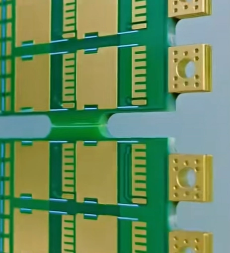
Rigid-flex qualification focuses on flex-to-rigid adhesion, bend-cycle endurance, and stable electrical continuity across transitions.
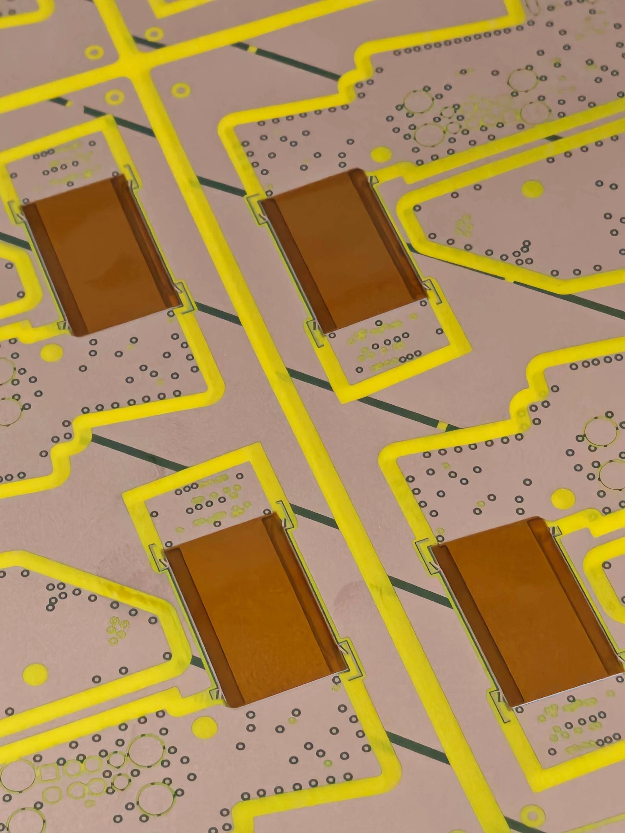
Qualification Materials & Compliance OverviewAcceptance & Reliability StandardsManufactured in accordance with IPC-6013 rigid-flex PCB standards, with additional process controls for flex-to-rigid adhesion, via reliability, and bend-cycle endurance. Material StandardsRigid sections use High-Tg FR-4 or low-loss FR-4 laminates for component stability, built with polyimide (PI) circuits and rolled-annealed copper. Optional coverlay or flexible solder mask enhances flex protection. Structural & Process CapabilitiesSupports multilayer custom rigid-flex stack-up design, controlled impedance routing across rigid-to-flex transitions, blind and buried vias, and selective stiffeners for mechanical reinforcement. ComplianceAll complies with RoHS / REACH, UL safety requirements IPC design guidelines, making the products suitable for medical, automotive, industrial, and aerospace electronics. |
KnownPCB Prototyping & Mass Production Service Ask for Support at Engineering
Higher unit cost at board level, but often lower total system cost.
|  |
 | Designed for mechanical reliability and electrical stability, not density alone.
|
KnownPCB Prototyping & Mass Production Service Ask for Support at Engineering
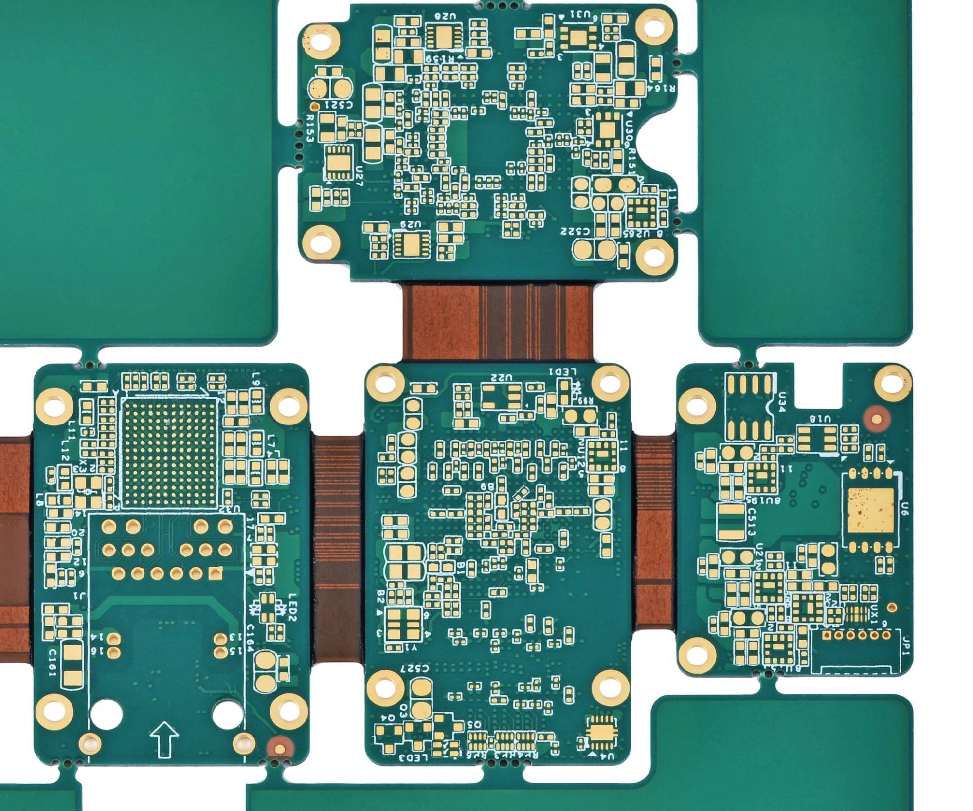
IPC 6013 Type 3/4 Rigid-flex circuits eliminate failure points inherent in discrete wiring, providing superior mechanical integrity and vibration resistance. We master complex Z-axis interconnect designs and utilize high-grade polyimide (Kapton) films, ensuring reliable dynamic flexing cycles up to 100,000. interconnects. Rigid-flex is rarely about flexibility alone. The following table focuses on stack-up structure, bend radius, material choices, and transition reliability—so you can evaluate whether your design benefits from rigid-flex integration, or if simpler flex or multilayer options would reduce risk and cost. KnownPCB Profile Ask for DFM Guideline |  |
| Parameter | BASIC | ADVANCED | HIGH-END | Complexity Trend | Classification Logic | Typical Use Case |
| Layer Count & Architecture | 2–6L, simple rigid-flex | 6–10L, multi-zone flex + rigid regions | 10L+, multi-zone, multi-stage HDI + full rigid-flex architecture | ↑ Layers & zone count | Layer Count / Structure | Engineer evaluates structural complexity |
| Number of Flex Zones | Single flex zone | 2–3 flex zones | Multi-zone flex + overlapping segments | ↑ Flex regions | Structure / Layout | Stack-up & routing planning |
| Transition Structure | Straight transition | Stepped transition | Complex 3D transition (bend + twist) | ↑ 3D mechanical complexity | Structure | Mechanical/structural co-engineering |
| Min. Trace / Space | ≈0.075 mm | ≈0.075 mm | ≈0.05 mm | ↓ Feature size | Material / Process | Designer evaluates manufacturability |
| Min. Mechanical Drill Size | 0.15 mm | 0.15 mm | 0.10 mm | ↓ Drill size | Structure | Drill / via process selection |
| Flex Bending Radius | R≥W×T | R≥W×T | R≥W×T | ↓ Bend radius | Functional / Flexibility | Validate bendability |
| Flex Life (Dynamic Cycles) | ≤10k cycles | 10k–50k cycles | ≥50k–100k cycles | ↑ Flex endurance | Functional / Reliability | One-time forming vs. dynamic flex applications |
| Rigid Core Material | High-Tg FR-4 | High-Tg FR-4 | High-Tg FR-4 / Megtron / Rogers | ↑ Material performance | Material / Process | Signal & reliability requirements |
| Flex Core Material | Standard PI | High-performance PI / PET | Ultra-thin PI / LCP | ↑ HF performance & flexibility | Material / Process | Flex zone reliability & RF capability |
| Flex Copper Type | RA/ED copper | RA/ED copper | High-ductility RA / ultra-thin copper | ↑ Dynamic reliability | Material | Dynamic bend zones |
| Adhesive System | Adhesive-based flex | Mixed adhesive / adhesive-less | Full adhesive-less or specialty adhesive | ↑ Thermal/impedance stability | Material | Reliability & SI control |
| Surface Finish | OSP / ENIG | ENIG / Immersion Silver | ENIG / ENEPIG / selective hard-gold | ↑ Finish precision & durability | Material | Connector fingers / critical pads |
| Impedance Control | ±10% | ±7–10% | ±5–7% | ↑ Tolerance precision | Functional / SI | High-speed routing design |
| Flex-zone Impedance Consistency | Basic control | Critical-path controlled | Critical + redundant paths dual-direction control | ↑ Flex SI difficulty | Functional / SI | Signal performance through bend zones |
| Operating Temperature Range | –20 to 85°C | –40 to 105°C | –40 to 125/150°C | ↑ Temperature grade | Functional / Reliability | Automotive / industrial |
| Reliability Standard | IPC-6013 Class 2 | IPC-6013 Class 2/3 | IPC-6013 Class 3 / AEC-Q100 | ↑ Certification grade | Functional / Quality | High-reliability applications |
| Service Tier | Rigid-Flex BASIC | Rigid-Flex ADV | Rigid-Flex PRO | ↑ Complexity & engineering effort | Tier / Capability | Procurement evaluates cost & complexity |
| Standard Lead Time | 7–15 days | 7–15 days | 7–15 days | ↑ Lead time | Schedule / Planning | Project planning |
| ZIF Contacts | Basic ZIF processing | Precision ZIF + chamfer | High-precision ZIF + selective thick-gold | ↑ Termination precision | Material / Process | Connector insertion durability |
| Flex Reinforcement | Simple PI stiffener | PI/FR-4/steel stiffener options | Multi-material composite stiffener + custom shapes | ↑ Reinforcement complexity | Structure / Process | Local support & stress control |
| 3D Forming Capability | Flat bending | Simple 3D bending | Complex multi-axis 3D forming | ↑ 3D forming requirements | Functional / Mechanical | Space-constrained products |
Industry-specificPCB SolutionsLearn about KnownPCB & Production equipments |
Do these FAQs cover flex stackup design, bend-radius limits, impedance control, and reliability testing to ensure cost-effective rigid-flex PCB production with stable quality and on-time delivery?
Yes, the FAQs support to find out the answer about rigid-flex PCB manufacturing, reliability testing, and production consistency while balancing cost, lead time, and quality at scale.
Proven by 7 industries, 4000+ customer projects
Please contact us at sales@knownpcb.com, ask for engineering support here or use the form below to reach out to KnownPCB | Get In Touch Today |