-- for SMEs Needing Serious Thermal Dissipation IATF 16949 Certified MCPCB Fabrication In China Since 2008
Whether you require standard aluminum core or high-power copper base boards for MOSFET arrays, our process ensures high dielectric strength
(> 3.0 KV) and reliable high-current paths.
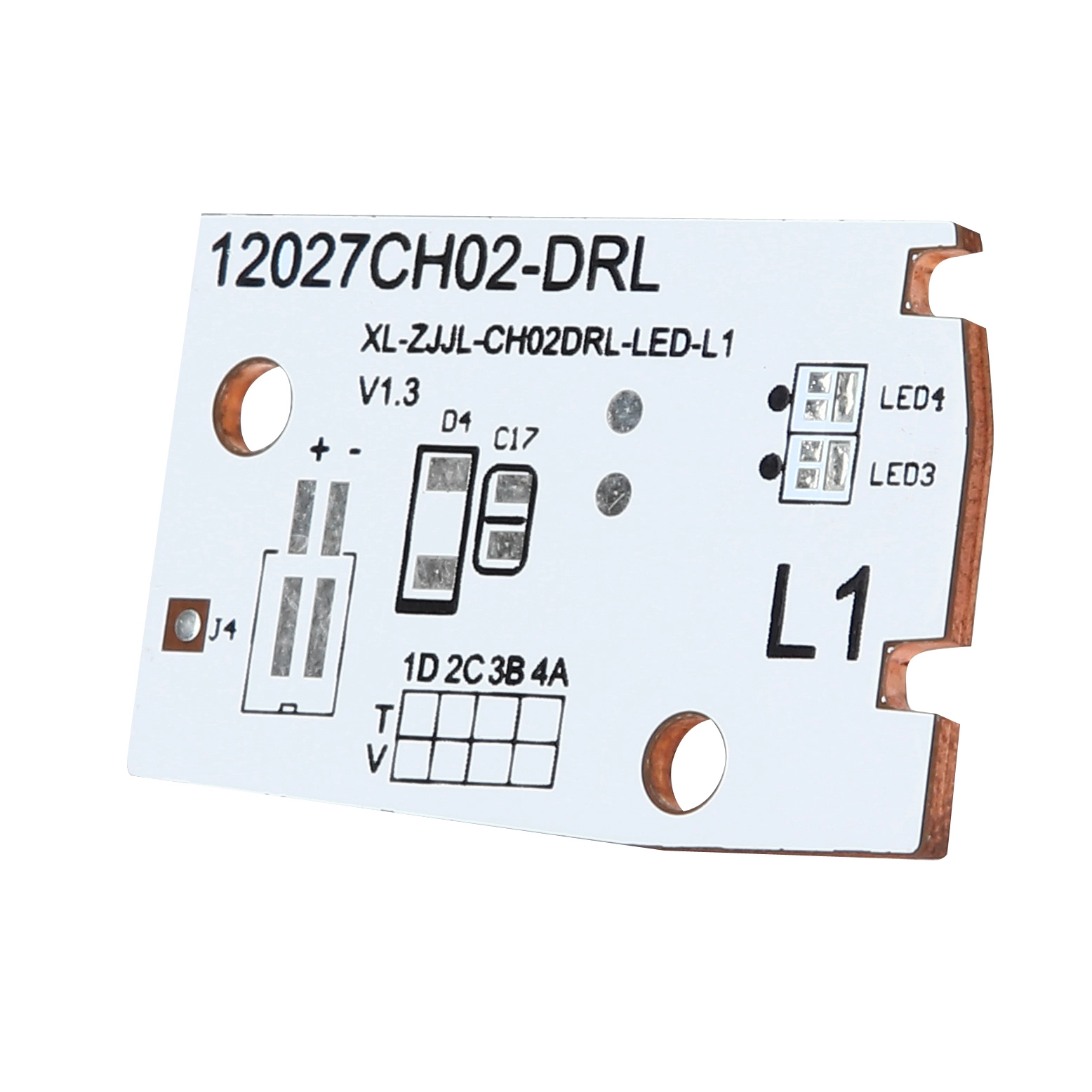
PCB with an aluminium or copper core used primarily for high-power LED and power driver thermal management.
Qualification, Materials & Compliance OverviewAcceptance Standards forManufactured to IPC-6012 guidelines adapted for metal-based boards and OEM-specific thermal test requirements. Material StandardsMetal base (Al or Cu), thermally conductive dielectric layer, copper foil; all materials traceable and UL-recognized where needed. Structure OverviewTypically single-sided or limited multilayer build on a metal core, with thermal vias and direct heat path to chassis or heatsink. ComplianceSupports RoHS / REACH, UL marking, and relevant safety and insulation requirements for lighting and power equipment. |
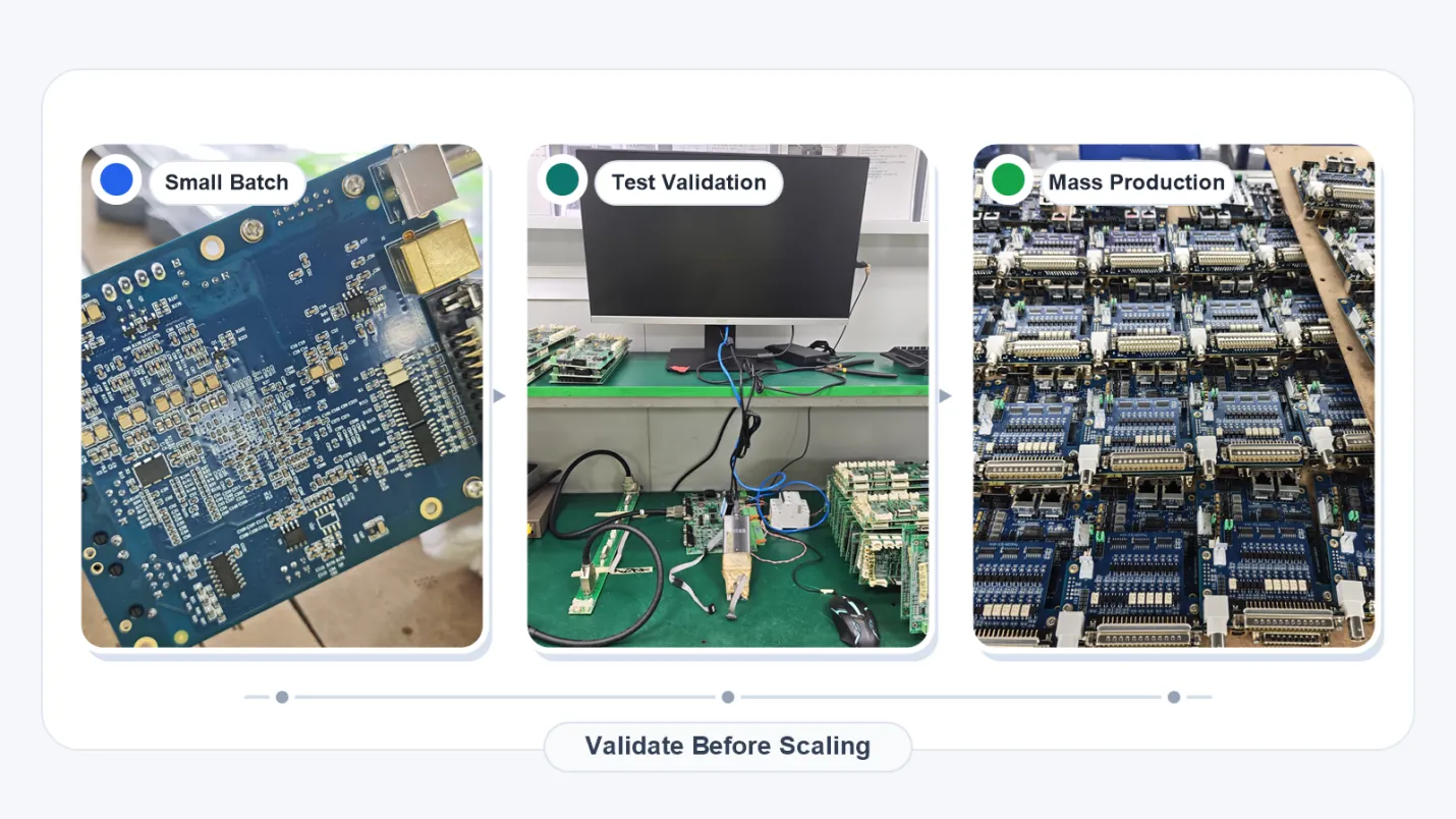
KnownPCB Prototyping & Mass Production Service Request Thermal Design Review
(Metal Core Printed Circuit Board)
More expensive than standard FR-4, but often cheaper than complex heat-sink assemblies.
|  |
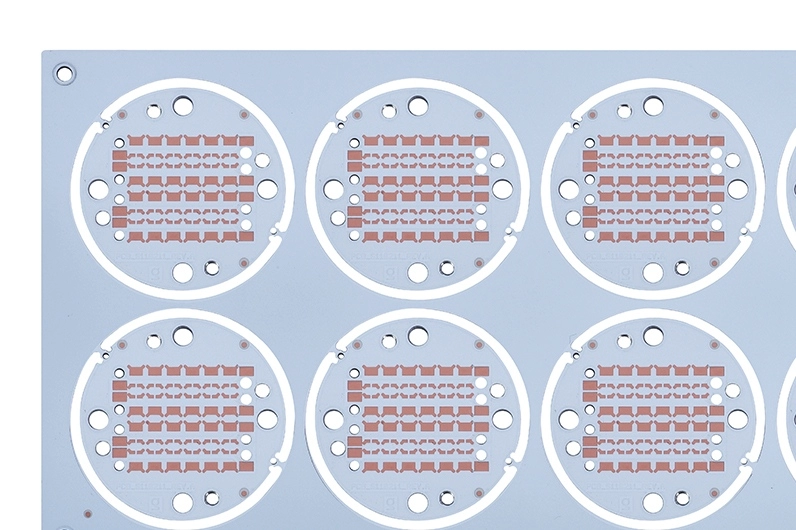 | Performance is driven by thermal capacity rather than routing density.
|
KnownPCB Prototyping & Mass Production Service Request Thermal Design Review
We consistently deliver MCPCB with high performance by utilizing premium dielectric layers with high thermal conductivity (k> 2.0W/m.K), minimizing thermal resistance (Rth). Thermal problems are usually structural, not schematic. These parameters focus on core material, dielectric thickness, thermal conductivity, and breakdown limits—so you can evaluate whether an MCPCB can manage heat, voltage, and mechanical mounting before finalizing LED or power-module layouts. KnownPCB Profile Ask for DFM Guideline | 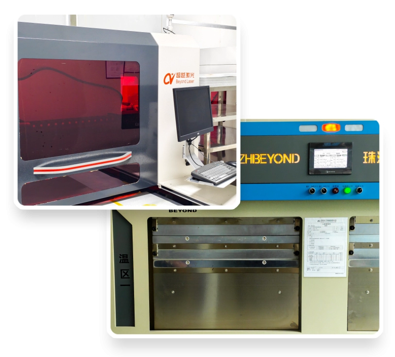 |
| Parameter | BASIC (Single-layer Aluminum MCPCB) | ADVANCED (High-thermal Aluminum MCPCB) | HIGH-END (Copper Core / Multilayer MCPCB) | Typical Use Case | Classification Logic |
| Layer Count | Single layer | Single / Dual layer | Dual-layer / Multilayer + localized thermal structures | Evaluating thermal path & routing space | Layer Count / Structure |
| Metal Core Material | Standard aluminum | High-thermal-conductivity aluminum alloy | Copper core / Specialty metal core | LED / Power module material selection | Material / Structure |
| Thermal Conductivity (k) | 1.0–3.0 W/m·K | 2.0–8.0 W/m·K | 3.0–10.0+ W/m·K | Thermal dissipation capability | Material / Process |
| Dielectric Thickness | 75–100 µm | 50–75 µm | ≤50 µm (down to 25 µm) | Balancing thermal resistance & dielectric breakdown | Material / Process |
| Copper Foil Thickness | 1–3 oz | 1–3 oz | 2–4 oz | High-current traces | Material / Process |
| Surface Finish | HASL / OSP | ENIG / OSP | ENIG / Hard Gold / Selective plating | Solder joint reliability & connector durability | Material / Process |
| Board Thickness | 0.8–1.6 mm | 1.0–2.0 mm | 1.5–3.0 mm (incl. copper core) | Structural strength & heatsink attachment | Structure / Mechanical |
| Mechanical Accuracy / Tolerances | Standard tolerances | Enhanced dimensional control | High-precision profiling + slotting | Mechanical assembly & heatsink fit | Mechanical / Process |
| Dielectric Breakdown Voltage | 500–1,000 V | 1,000–2,000 V | >2,000 V | High-voltage LED drivers / Power supplies | Functional / Performance |
| Operating Temperature | –20 to 85 °C | –40 to 105 °C | –40 to 125 / 150 °C | Automotive lighting / Industrial / New energy | Functional / Performance |
| Thermal Cycling Life | Standard grade | Mid-grade | Automotive/Industrial-grade cycling life | Long-term reliability | Functional / Performance |
| Service Tier | MCPCB BASIC | MCPCB ADV | MCPCB PRO | Quick selection by application & power level | Tier / Capability |
| Standard Lead Time | 3–10 days | 3–10 days | 5–20 days | Project scheduling | Lead Time / Planning |
| Localized Heavy-copper Regions | Not supported / Limited | Localized copper thickening (selective) | Embedded copper blocks / Complex localized copper structures | High-power hotspot design | Material / Process |
| Slotting / Thermal Windows | Simple mechanical slots | Polygon thermal windows | Complex CNC machining / Recessed cavities | Heatsink bonding & insulation clearance | Mechanical / Process |
Industry-specificPCB SolutionsLearn about KnownPCB & Production equipments |
Are thermal paths and dielectric thickness properly defined for metal core PCB manufacturing?
These FAQs outline MCPCB stackup options, heat dissipation performance, insulation reliability, and production tolerances, helping ensure stable quality, cost control, and consistent delivery.
Proven by 7 industries, 4000+ customer projects
Please contact us at sales@knownpcb.com, ask for engineering support here or use the form below to reach out to KnownPCB | Get In Touch Today |