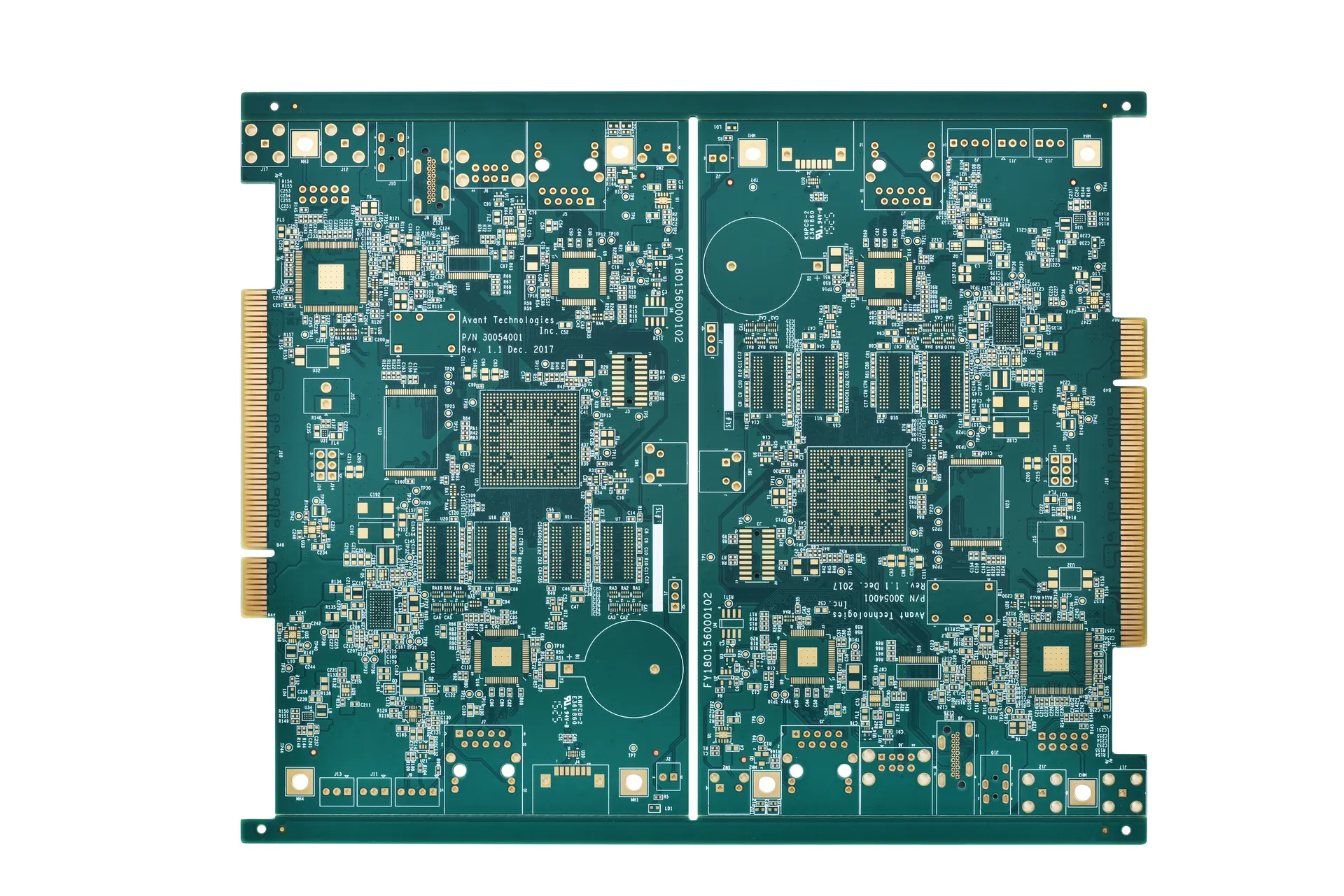
KnownPCB provides fast flex PCB prototype and flex circuit board fabrication in China for global OEMs.
Get quick turnaround, reliable quality, and cost-effective manufacturing for custom flex PCB projects.
Consult our Application Engineers (AEs)
in designing an optimized stack-up that balances Dk stability with budget for 5G small cell prototype development.
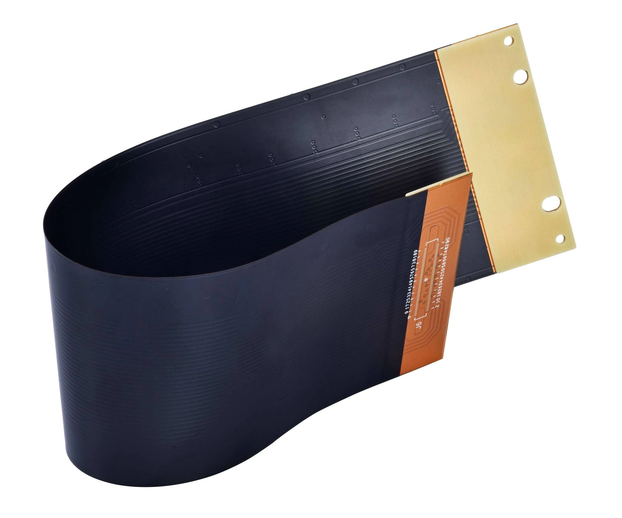
Thin and flexible interconnect designed to meet dynamic or static flex zones while also reducing connectors and wire harnesses.
View KnownPCB's Qualification Materials & ComplianceAcceptance StandardsFabricated and inspected according to IPC-6013/IPC-A-600 for flexible circuitry fabrication and inspection. Material StandardsPolyimide base film featuring either rolled copper, adhesive systems, or adhesive-less systems that meet these specifications where applicable and UL listed when applicable. Structure OverviewCopper layers on a flexible dielectric with coverlay, stiffeners and defined bend areas ensuring. ComplianceSupports Halogen-free, RoHS/REACH and Flammability requirements of consumer and industrial electronics products. |
KnownPCB Prototyping & Mass Production Service Ask for DFM Guideline
Costly per cm2, yet cost-effective when replacing discrete interconnect assemblies.
|  |
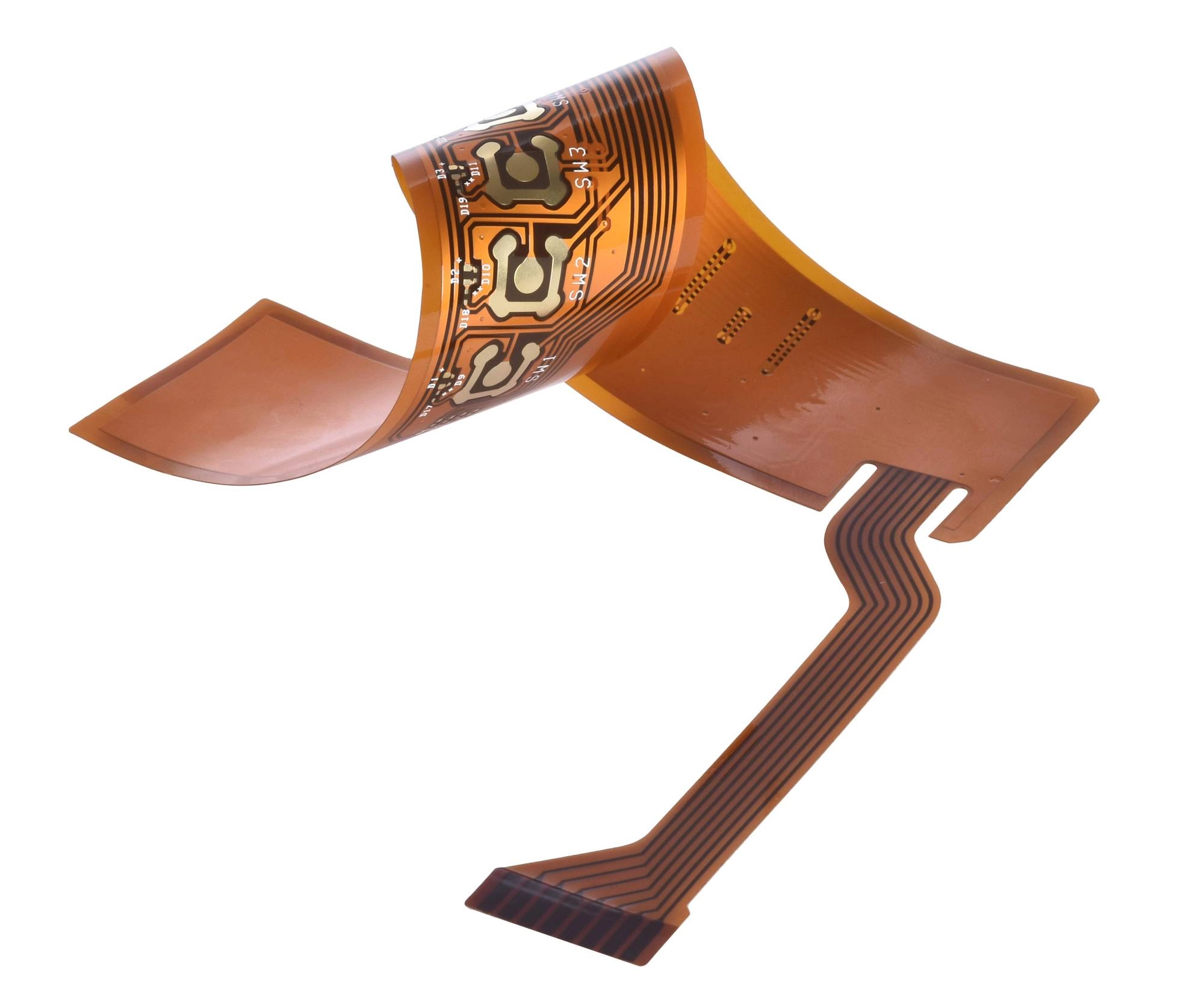 | Mechanical freedom and short, noiseless links provide immense performance value.
|
KnownPCB Prototyping & Mass Production Service Ask for DFM Guideline
FPC designs that function perfectly on paper don't always translate seamlessly to production. Manufacturing constraints, material behavior and mechanical stress must all be taken into account early. Below are several technical parameters which can help evaluate whether a flexible printed circuit design can support stable and scalable manufacturing. To avoid costly re-spins, you need to check these critical manufacturing parameters first:
KnownPCB Profile Ask for DFM Guideline
|  |
| Parameter | STANDARD (Single/Dual-Layer Flex) | ADVANCED (Dual to ≤4-Layer Flex / Semi-Rigid) | MICRO (4–8 Layer Flex / High-density / Rigid-Flex Hybrid) | Typical Use Case |
| Layer Count | 1–2 layers | Confirm for the specified stack-up during project review. | Confirm for the specified flex/rigid-flex stack-up during project review. | Engineer evaluates manufacturability & stack-up |
| Min. Trace / Space | ≈0.075 mm | ≈0.075 mm | ≈0.05 mm | Manufacturability review (DFM) |
| Min. Drill / Via Size | ≈0.15 mm | ≈0.10 mm | ≈0.05 mm | Drill/stack-up selection |
| Min. Bending Radius | R ≈ 10–12× thickness | R ≈ 8–10× thickness | R ≈ 5–8× thickness | Designer validates bendability |
| Static/Dynamic Flex Life | Confirm for the specified stack-up, flex region, bend conditions, and test requirements during project review. | Confirm for the specified stack-up, flex region, bend conditions, and test requirements during project review. | Confirm for the specified stack-up, flex region, bend conditions, and test requirements during project review. | Engineer & buyer validate lifecycle |
| Base Material | PI / PET | PI / PET / High-Tg FR-4 (semi-rigid) | High-Tg FR-4 / PI / LCP / Rogers | Designer defines material stack |
| PI Thickness | 25–50 µm | 12.5–25 µm | 8–12 µm (ultra-thin PI) | Flexibility / stack thickness planning |
| Copper Type (RA/ED) | RA / ED copper mix | RA / ED copper mix | High-ductility RA copper | Fatigue resistance for dynamic flex |
| Copper Weight | 0.5–1 oz | 0.5–2 oz | 1–2 oz | Designer selects load capacity |
| Adhesive System | Adhesive-based FPC | Mixed adhesive + adhesive-less | Fully adhesive-less system | Affects thickness, thermal stability, impedance |
| Coverlay Thickness | 25–50 µm | 12.5–25 µm | 12.5 µm + laser-defined openings | Pad opening accuracy & flex reliability |
| Dielectric Thickness | 50–100 µm | 25–75 µm | 12.5–25 µm | Impedance / stack-up thickness |
| Surface Finish | OSP / ENIG | ENIG / HASL / Immersion Silver | ENIG / Hard Gold / Selective Gold (for contact pads) | Solder reliability & connector interface |
| RF Material Capability | None | Low-loss PI | LCP (Dk ≈ 2.9, Df ≈ 0.002) | RF cable replacement / antenna flex |
| Impedance Tolerance | ±10% | ±7–10% | ±5–7% | Signal integrity compliance |
| Electrical Test | Flying probe | Flying probe + fixture test | Flying probe + fixture + high-voltage test | Buyer/engineer reliability verification |
| Total Flex Life | Total flex life is confirmed by project review for the specified stack-up, flex region, bend conditions, and test requirements. | Total flex life is confirmed by project review for the specified stack-up, flex region, bend conditions, and test requirements. | Total flex life is confirmed by project review for the specified stack-up, flex region, bend conditions, and test requirements. | Buyer validates service life |
| Operating Temp | ≈130°C | ≈150°C | ≈180–260°C | Industrial / automotive / high-density packaging |
| Certification | IPC-6013 Class 2 | IPC-6013 Class 2/3 | IPC-6013 Class 3 / AEC-Q200 | Engineering & procurement quality alignment |
| Service Tier | FPC STANDARD | FPC ADVANCED | FPC MICRO | Procurement cost/complexity estimate |
| Lead Time | 7–10 days | 10–15 days | 14–20 days | Project planning |
| Lamination / Bonding | Single lamination | Dual lamination | Multi-layer lamination | Designer defines bonding reliability |
| Gold Fingers / SMT Pads | Optional | Standard | High-precision / selective hard-gold | Solderability & connector life |
| Outline / Cutting | V-cut / R-cut | Laser cutting | High-precision contour cutting | Used for complex mechanical shape |
Get a FREE DFM Review on Your Design (24-Hour Feedback)
Layer count and bend life depend on the stack-up, flex region, and test conditions. Confirm these values after engineering review.
Industry-specificPCB SolutionsLearn about KnownPCB & Production equipments |
FAQs about flexible printed circuit designs may also provide guidance.Knowing these cost drivers helps optimise a design without compromising performance or reliability.
For deeper technical discussions, feel free to reach out to KnownPCB.
Proven by 7 industries, 4000+ customer projects
Please contact us at sales@knownpcb.com, ask for engineering support here or use the form below to reach out to KnownPCB | Request a Manufacturing QuoteInclude your quantity, target delivery date and key requirements. File handling and NDA information. |