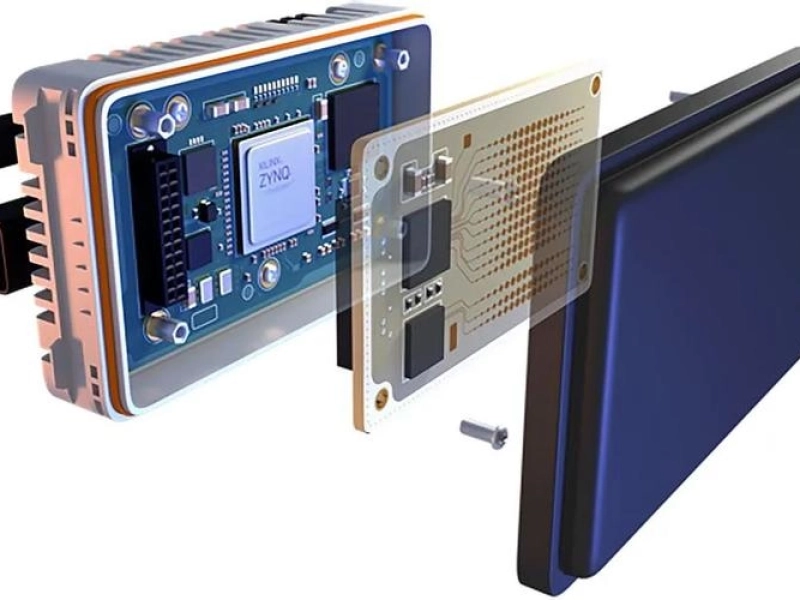
THT is straightforward, Through‑hole assembly (also known as THT – Through‑Hole Technology) is a key PCB assembly method where components with leads are inserted into drilled holes and soldered for robust electrical and mechanical connections. This article breaks down clearly THT PCB assembly capabilities and provides a practical THT DFM review checklist that should be verified before manufacturing by KnownPCB.
| Process | Describe | Standard Basis |
|---|---|---|
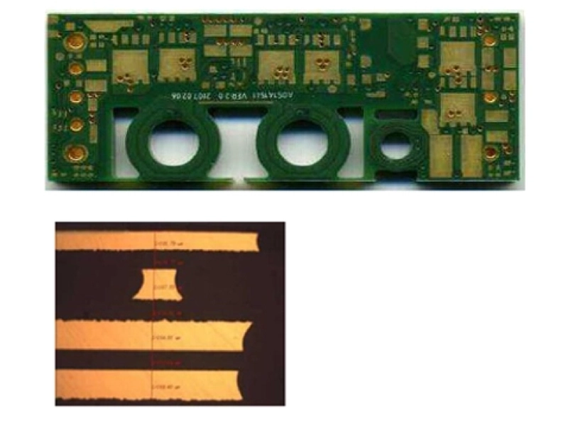
| Drilling | Through holes are machined using a CNC drilling machine, with a diameter accuracy of ±0.01mm, to accommodate component leads. | IPC-A-610H 8.2.1 |
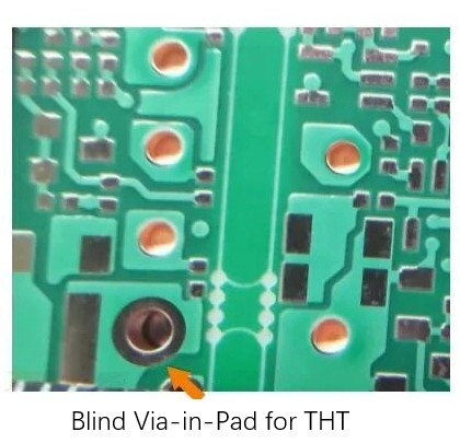
| Hole metallization | The hole walls are thickened by chemical copper plating followed by electroplating (25–50 μm) to form conductive pathways, enabling interconnection of inner layers in multilayer boards. | IPC-J-STD-001J 4.5.2 |
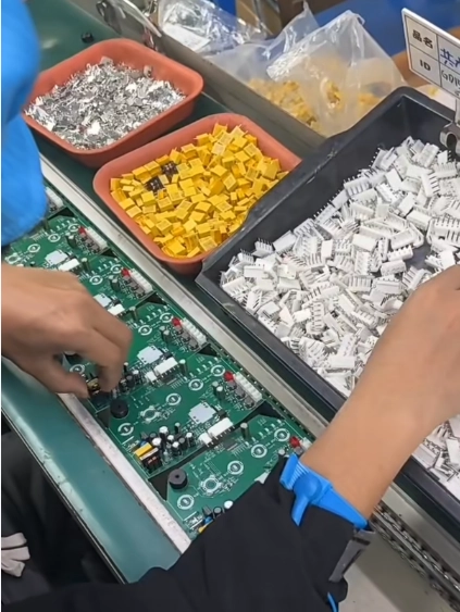
| Component insertion | - Axial leads: Resistors, diodes, leads extend along the axis, horizontal mounting. - Radial leads: Capacitors, LEDs, leads extend vertically, saving space. - DIP/SIP packages: Commonly used dual in-line/single in-line packages for integrated circuits, positioned by automated insertion machines. | IPC-A-610H 8.1.1–8.1.3 |
| Pin cut | After soldering, trim any excessively long leads, leaving 0.5–1.0 mm of protrusion. | IPC-A-610H 8.2.4 |
| Welding | - Wave soldering: The mainstream method for mass production, where molten solder is applied to the bottom of the PCB through a wave of solder. - Manual soldering: Used for small batches, rework, or high-power components (such as transformers and connectors). - Selective wave soldering: Precisely sprays solder, suitable for mixed SMT and THT boards, reducing heat damage. | IPC-J-STD-001J 5.3.1–5.3.4 |
Submit Your Throguh-Hole PCB Project
| Item | Sub-item | Standard Capability | Limited Capability | Remark |
|---|---|---|---|---|
| DIP Process (Wave soldering) | PCB Size - Min Size | L≥30mm, W≥30mm | L<30mm | |
| PCB Size - Max Size | L≤650mm, W≤400mm | L:800-650mm, W:400-450mm | ||
| PCB Size - Thinnest Size | 0.4mm | T < 0.4mm | ||
| PCB Size - Thickest Size | 5mm | T > 5mm | ||
| Conformal Coating Process | Temperature range | -30℃ ≤ T ≤ 120℃ | -50℃ ≤ T ≤ 150℃ | |
| Coating thickness | 20um ≤ T ≤ 35um | 35um ≤ T ≤ 60um |
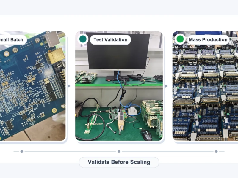
Before sending your PCB to manufacturing, the following DFM review points must be checked to ensure reliable THT assembly and optimal yield.
| Applications | Typical Components | Technical Advantages | Standard Basis |
|---|---|---|---|
| Industrial control equipment | Power connectors, relays, terminal strips | Strong vibration and shock resistance; mating/unplugging cycles > 750 times | IPC‑A‑610H 8.1.1 |
| Automotive electronic systems | Motor controllers, ECU power modules, high‑current connectors | High mechanical strength; good thermal cycling stability | IPC‑A‑610H Class 2/3 |
| Power & Power Modules | Transformers, inductors, high‑power electrolytics | High current capacity and reliable heat dissipation | IPC‑J‑STD‑001J 5.3.2 |
| Military & Aerospace | Radar, navigation, satellite power systems | Extreme environmental adaptability; long‑term reliability | NASA‑STD‑8739.3 13.6.2 |
| Medical equipment | ECG monitors, defibrillators, diagnostic interfaces | Low failure rate; repairable solder joints | IEC 60601‑1 + IPC‑A‑610H |
| Communication base stations | RF filters, high‑power amplifiers | High power density; excellent thermal expansion match | IPC‑A‑610H 8.2.4 |
Work with KNOWNPCB to Start your THT Assembly Project
For more on SMT assembly and PCB testing, or to request a professional THT DFM review for your design files, contact us today!
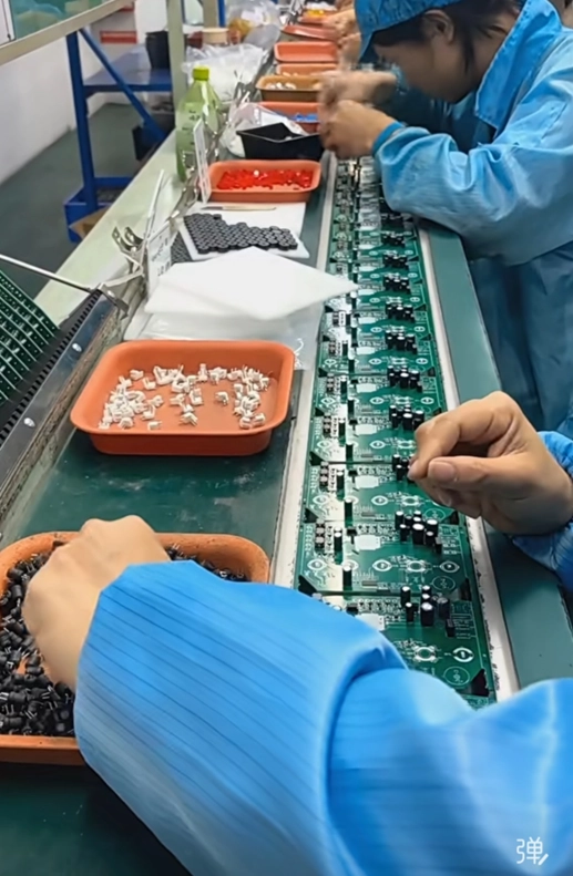
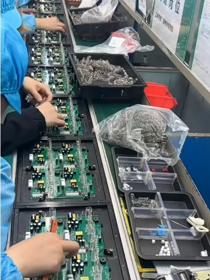
Request for a Virtual Tour of the Through-hole Assembly Workshop Tour