Okay, the design, manufacturing, and use of PCBs (printed circuit boards) in industrial control have unique requirements and characteristics.
The following is a detailed introduction to the key aspects about industrial PCB:
High reliability: This is the primary requirement. Industrial control systems (such as PLCs, DCSs, frequency converters, servo drives, HMIs, sensor interfaces, etc.) typically need to operate continuously 24/7 for years, or even decades. Any PCB failure can lead to production line shutdowns, safety accidents, or significant economic losses. Therefore, PCB design, material selection, and manufacturing processes must all be geared towards long-term stable operation.
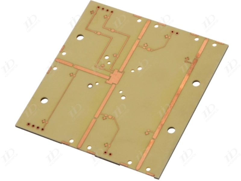
KnownPCB Industrial PCB Solution
Wide temperature range: Industrial PCB needs to withstand extreme temperature changes (e.g., -40°C to +85°C or even higher), while consumer-grade PCBs are typically between 0°C and 70°C.
High humidity, dust, and chemical corrosion are common in factory environments. Industrial PCBs require protection (such as conformal coating), and the materials themselves must be more corrosion-resistant.
Vibration and shock: Vibration and shock will occur during equipment operation and transportation. PCB design (component layout, mounting method), materials (high Tg board), and soldering processes (such as selective soldering, underfill adhesive) all need to enhance mechanical strength.
Electrical noise and interference: Industrial environments are filled with strong electromagnetic interference (EMI) generated by high-power motors, frequency converters, relay switches, etc. PCB design must prioritize electromagnetic compatibility (EMC) to ensure strong immunity to interference and minimal external radiated interference.
Industrial equipment has a long lifespan, so industrial PCB design needs to consider the long-term supply capacity of key components.
Sometimes this kind of PCB is necessary to use more mature (maybe not the latest) but stable supply and well-proven reliability devices.
It must comply with strict industrial safety standards and industry specifications (such as IEC/UL standards, functional safety standards IEC 61508 / ISO 13849, etc.).
The design needs to consider safety isolation (such as high and low voltage isolation), redundancy design, and fail-safe mechanisms.
High Tg value:
Substrates with high glass transition temperatures (such as FR-4 High Tg, typically ≥170°C) maintain better mechanical and electrical stability at high temperatures, reducing the risk of warping and delamination.Low CTE: Low coefficient of thermal expansion, matching the CTE of components (especially BGA, etc.), reducing solder joint stress failure caused by temperature cycling.
Low-loss/high-frequency board material: For high-speed signals (such as high-speed communication, servo control) or RF applications, special board materials with low dielectric loss (Low Dk/Df) are required (such as Rogers, Isola, etc.). FR-4 standard board materials have higher losses at high frequencies.
Thick copper: Used in high-current paths (such as power supplies and motor drives) to reduce heat generation and voltage drop. Commonly available starting from 1 oz, 2 oz, 3 oz or even higher.
Special requirements for sheet materials: CAF (conductive anode wire) resistant, high CTI (tracking index) resistant, etc.
Layered structure in industrial PCB:
Typically, there are multiple layers (4+) to provide a complete ground and power plane, optimizing signal integrity and EMC performance.
Carefully plan the stacking sequence, control the impedance (differential pairs, high-speed single-ended signals), and minimize crosstalk.
Zoning: Clearly divide the area into analog zone, digital zone, power zone (high voltage/low voltage), and high frequency zone. Physical isolation and ground plane segmentation are common methods.
A low-impedance power distribution network (PDN) uses decoupling capacitors of sufficient capacitance (different capacitance values and package combinations) placed close to the IC power pins.
The power supply plane is designed reasonably to avoid bottlenecks.
High-speed signal traces control impedance (differential line pairs are of equal length and have the same distance from the reference plane).
Avoid via stubs to reduce signal reflection.
Minimize loop area (tight coupling between signal line and return path) to reduce radiation and sensitivity.
Keep critical signal lines away from noise sources (clock, switching power supply, power lines).
The heat-generating components (power devices, power ICs) are arranged in a reasonable manner, making full use of the PCB copper foil for heat dissipation (heat dissipation pads, heat dissipation via arrays).
Consider the connection to the heat sink and the heat path.
Filtering: Use filtering circuits (LC filters, common mode inductors, TVS diodes, ferrite beads, etc.) at the power input and signal interface.
Shielding: Use shielding covers (partial or overall) when necessary.
Grounding: Establish a good grounding system (choose between single-point and multi-point grounding strategies), minimize ground loops, and ensure low-impedance grounding paths. Proper grounding is the cornerstone of EMC design.
Interface protection: ESD, surge, and EFT protection designs are implemented for communication ports (RS485, CAN, Ethernet) and I/O ports.
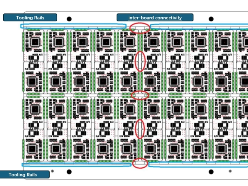
Design for manufacturability: Consider the factory’s actual process capabilities (minimum linewidth and spacing, hole diameter, etc.) to avoid overly complex designs that are difficult to maintain stable production.
Industrial/Automotive grade: Prioritize components with wide temperature range, long lifespan, and high reliability (-40°C to +85°C/+125°C).
Long supply cycles: Focus on the supply stability of key components (MCU, application-specific IC).
Power devices: MOSFETs/IGBTs and their drivers must meet voltage, current, and switching speed requirements, and heat dissipation must be considered.
Connectors: Select models that are robust and reliable, have good contact, and whose protection rating (IP rating) meets the requirements (such as D-Sub, M12/M8, Phoenix terminals, etc.).
High-precision manufacturing (line width and spacing, interlayer alignment).
Strictly control the copper thickness and plating thickness.
Reliable soldering processes (such as lead-free soldering, which may require high-temperature solder paste) ensure soldering quality and reduce cold solder joints and poor solder joints.
High-standard cleaning to remove flux residue (to avoid corrosion and leakage).
Commonly used plating methods include immersion gold (ENIG), immersion tin, electroplated nickel gold (hard gold plating for gold fingers/contacts), and OSP.
When making a selection, factors to consider include solderability, corrosion resistance, contact resistance, cost, and suitability for fine-pitch components (such as BGAs).
Conformal coating: A layer of insulating protective varnish (acrylic, polyurethane, silicone, epoxy resin, etc.) is applied to the surface of a PCB to provide protection against moisture, dust, salt spray, chemical corrosion, mold, and insulation. It is commonly used in harsh industrial environments.
Conformal coating: This is a specific type of conformal coating application.
AOI: Automated Optical Inspection (solder joints, component placement).
ICT/Flying Probe: Online testing (electrical connectivity, basic component values).
FCT: Functional Testing (simulating actual working conditions to test the overall board functionality).
Aging test: High-temperature power-on operation to screen for early failures.
Temperature cycling test: Simulates temperature changes to test the reliability of materials and solder joints.
Vibration testing: Simulates vibrations during transportation and use.
High-acceleration life testing: used for reliability prediction (high cost, typically used for design verification or critical products).
Programmable Logic Controller (PLC): The mainboard and I/O modules of a PLC.
Distributed control system: DCS controller card, I/O card, communication card.
Inverter/servo drive: core control board, power drive board.
Human-Machine Interface (HMI): Main control board and display driver board.
Industrial robots: controller, joint drive board, sensor interface board.
Instrumentation: Data acquisition card, sensor signal conditioning board.
Motor controller: Stepper/DC/brushless motor driver.
Communication gateway: a conversion and interface board for industrial Ethernet and fieldbus (Profinet, EtherCAT, CANopen, etc.).
Power modules: Industrial-grade power supplies (AC-DC, DC-DC).
The core of industrial control PCBs lies in achieving long-term, stable, reliable, and safe operation in harsh environments . This requires high standards and stringent requirements in every aspect, from design concepts, material selection, component selection, manufacturing processes, protective measures to testing and verification . It differs significantly from consumer electronics PCBs, typically being more expensive and having longer design cycles, but stability is its uncompromising lifeline.
If you have specific application scenarios (such as making PLC modules, servo drives, etc.) or encounter specific design/manufacturing problems, you can ask further questions, and I can provide more targeted information.
Request for a tech support
 | Download our design guidesfor better PCB designing and manufacturing These are some of the design guides designers and engineersdownload the most:
|
Proven by 7 industries, 4000+ customer projects
Please contact us at sales@knownpcb.com, ask for engineering support here or use the form below to reach out to KnownPCB | Get In Touch Today |