High Tg FR-4 Material Selection for Industrial PCBs
When it comes to picking the right PCB substrate, it’s never just about the specs—it's about strategic decision driven by the end-use environment. Because of this, the sweet spot for most high-reliability industrial PCBs lies in High Tg FR-4. If your product faces extended thermal cycling or requires repeated lead-free soldering, aiming for a Tg of 150°C to 170°C isn't just a recommendation, it’s a necessity for long-term stability. Beyond just the Tg rating, you should prioritize the following key metrics:
| Parameter | What to Look For |
|---|---|
| Tg — Glass Transition Temperature | A Tg of ≥150°C or ≥170°C is recommendation, depending on the product’s reliability level and operating environment. |
| Td — Decomposition Temperature | Pay attention to the 5% weight-loss temperature. A higher Td generally indicates better resistance to thermal degradation. |
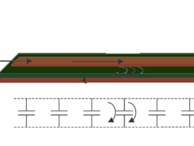
| Z-axis CTE | A lower Z-axis CTE helps reduce thermal stress on plated through holes, hole-wall copper, and interlayer structures. |
| T260 / T288 / T300 | These parameters help show whether the laminate can stay stable without delaminating at high temperatures. |
| Moisture Absorption | Less moisture absorption is helpful to maintain insulation performance, reduces CAF risk, and lead-free soldering. |
| CAF Resistance | It is especially important for high-density designs, multilayer boards, and products used in humid environments. |
| Flammability Rating | UL 94 V-0 is typically required for most industrial applications. |
| IPC Material Reference | Relevant IPC-4101 slash sheets can be used as practical references when specifying the laminate, such as IPC-4101/21, /24, /26, etc. |
Representative high-Tg FR-4 materials include Isola FR406, Shengyi S1000-2M, and similar laminate systems offer a high Tg of 170°C and superior resistance to lead-free soldering—essential for complex multilayer industrial and communication modules. they can take a beating from lead-free soldering without breaking a sweat.
It will be significantly lowers the risk of Z-axis expansion issues if choosing these materials of industrial-grade PCBs. Because of these properties, this kind of industrial-grade PCB materials are suitable for multilayer industrial control PCBs, power control boards, communication modules, and and other products that require stable long-term performance.
However, the final PCB material approval should always be a balance between the official datasheet and your PCB fabricator's process limits. It’s about aligning the industrial-grade PCB material’s performance with the specific reliability demands of your client.
Polyimide Substrates for FPC and Rigid-Flex Applications
For applications where the PCB must support bending, compact assembly, or rigid-flex integration, Polyimide becomes a more suitable substrate choice than conventional FR-4.
Polyimide substrates, or PI, are usually selected whenever you need flexibility, compactness, or complex interconnects.
Leveraging its superior thermal stability and bendability, we frequently see Polyimide (PI) substrates being used in high-reliability sectors—think Battery Management Systems (BMS), automotive camera modules, and complex rigid-flex assemblies. It is the ability to support thin-film connectivity that makes PI essential for any project requiring compact, high-reliability interconnects.
When PCB designers or Product Managers select a PI material, not only the PCB material, but also evaluate soldering, humidity, mechanical stress, and long-term temperature changes in real FPC and rigid-flex industrial applications. So, the following delivery requirements and material characteristics will be cross-checked during specification and qualification.
Polyimide Material Delivery Requirements and Characteristics
| Item | Recommended Considerations |
|---|---|
| Operating Temperature Range | According to the products’ requirement, the material meets -40°C to 125°C operating requirements, or a higher temperature rating. |
| Short-Term Solder Heat Resistance | We must ensure the material is compatible with lead-free soldering and the defined assembly process conditions. |
| Copper Foil Thickness | The selection of copper foil thickness is driven by the current-carrying capacity and flexibility requirements. The common options of copper thickness include 12 μm, 18 μm, and 35 μm. |
| Peel Strength | The evaluation of peel strength provides a window into the bonding reliability between the copper foil and PI film. |
| Flexural Life | It is required for dynamic bending and static bending to specified separately. |
| Moisture Absorption | The moisture absorption is a key factor that impact on insulation performance and dimensional stability. |
| Flammability Rating | We treat the flammability specs as a non-negotiable baseline that against the system’s safety needs. |
| Halogen-Free Requirement | In KnownPCB’s experience, chlorine, bromine, and total halogen content may be controlled in accordance with IEC 61249-2-21 or customer specifications. |
| FPC Material Standards | When we vet material selection and verification, the reference IPC-4202, IPC-4203 are industry-standard frameworks, or applicable customer material specifications. |
Where halogen-free compliance is required, the industrial-grade PCB material may typically be in check according to the following limits: Cl ≤900 ppm, Br ≤900 ppm, and total halogen content ≤1500 ppm. KnownPCB would also suggest confirming the key design details as early as possible, including the stack-up, bend radius, copper foil type, coverlay, stiffener, impedance control, and reliability test conditions.
Industrial and Automotive-Grade Component Selection for PCBA
Component selection for industrial PCBA projects is far more than basic electrical specs, it requires Temperature range, expected service life, package reliability, supply continuity, and the original manufacturer’s quality grade all matter.
Industrial-grade parts work well for common industrial equipment. But the challenging operation condition in high-temperature, outdoor systems, automotive applications, new energy equipment, rail transit, or other high-reliability scenarios, KnownPCB would generally recommend considering automotive-grade or higher-grade components.
In our view, the following reference can be a instruction:
The auto component goes well beyond wider range of temperature, it encompasses AEC-Q reliability testing, batch consistency, change control, PPAP, or customer approval processes. In practice, the final decision on the components always come back to the manufacturer’s datasheet, reliability documentation, and the customer’s qualification requirements.
Typical Temperature Range and Component References
| Component Type | Typical Industrial Temperature Range | Typical Automotive Temperature Range | Main Reference |
|---|---|---|---|
| MCU / Controller | -40°C to 85°C | -40°C to 125°C or higher | AEC-Q100, component datasheet |
| Aluminum Electrolytic Capacitor | -40°C to 105°C | -40°C to 125°C | IEC 60384-4, component datasheet |
| MOSFET | -40°C to 150°C | -40°C to 175°C | AEC-Q101, JEDEC JESD22, component datasheet |
| Power Module | -40°C to 85°C | -40°C to 105°C / 125°C | Module datasheet, customer specification |
| Resistors, Inductors, Ceramic Capacitors | -40°C to 85°C / 105°C | -40°C to 125°C / 150°C | AEC-Q200, component datasheet |
Component Derating Guidelines for Long-Term Industrial Reliability
Many industrial PCBA products are designed with 5 to 10 years of operation, sometimes even longer.
Because of this, derating is helpful to keep components away from their absolute limits under real working conditions. In practice, this gives the design more margin, lowers the chance of early failure, and supports better reliability over time.
The following values serve as a typical engineering guideline for industrial control applications. Designers overlay these with internal derating standards, customer requirements, datasheets, operating temperature, heat dissipation, and reliability calculations.
Typical Voltage, Current, and Power Derating Guidelines
| Component Type | Voltage Derating | Current / Power Derating | Temperature Notes |
|---|---|---|---|
| Aluminum Electrolytic Capacitor | ≤90% | Ripple current ≤80% | A rule of thumb is to keep operating temperature staying at least 10°C–15°C below the rated upper limit. |
| Tantalum Capacitor | ≤50%–70% | ≤70% | Avoid surge current and full-load operation at high temperature. |
| MLCC | ≤50%–80% | — | It is essential to scrutinize DC bias and thermal characteristics to ensure sufficient margins, while managing placement to mitigate mechanical cracking. |
| MOSFET | Vds ≤80% | Id / Pd ≤70% | Ensure a conservative Tj margin to prevent long-term degradation from operating near thermal limits |
| Power Module | Input / output voltage ≤85% | Output current ≤70%–80% | Adherence to the derating curve is necessity for high-temperature reliability. |
| Resistor | Working voltage ≤70% | Power ≤50%–70% | Derating is required when used at elevated temperatures. |
| Connector | Rated current ≤70%–80% | — | Check temperature rise, mating-cycle life, and contact resistance. |
Need Support with Industrial PCB Material Selection?
KnownPCB helps review PCB stack-up, material selection, soldering conditions, component grade, and reliability requirements for industrial, automotive, power, and communication applications.
Contact KnownPCB