Blog & Design Guide

A rigid-flex transition zone needs more than a line separating green and amber areas in a layout. The rigid dielectric ends, the flexible layers continue, and protective or bonding materials may terminate at different positions. Those boundaries affect where the circuit can bend and where holes, pads, and mechanical supports can be placed.
Review the boundary as a group of related geometries. Start with the finished rigid outline, then locate the flex outline, coverlay termination, rigid-material cutback, and intended bend start. Some features may overlap and others require separation. Their relation should come from the agreed stack and fabrication process, with dimensions referenced to a common datum.
On this page
Define the rigid and flex regions in the design data, then provide a fabrication view that a supplier can read without interpreting artwork colors. Give each region a name and associate it with the corresponding stackup. A layer that continues through a rigid island is different from one that ends there; that distinction must remain clear when files are exported.
KnownPCB's rigid-flex PCB manufacturing page describes the product scope. Use a project drawing to communicate how that scope applies at every transition. A repeated region can share one detail only when its construction and geometry are genuinely the same. Otherwise, give the exceptions separate identifiers and views.
The product image shows rigid islands connected through flexible material. It helps explain the physical arrangement, but it cannot reveal the exact cutback, coverlay overlap, or resin boundary inside the board. Those features need dimensioned fabrication information and, where required, inspection evidence at a specified location.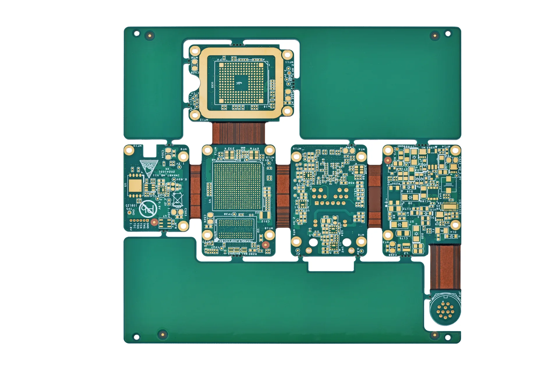
Rigid sections and flexible links are visible, while the exact material termination must come from the fabrication drawing.
Avoid duplicating an edge in several files without a declared reference. If the mechanical outline, coverlay artwork, and fabrication detail show slightly different boundaries, the fabricator has to stop and ask which one controls. Resolve the discrepancy in the released package. An undocumented interpretation can become a problem when another supplier or another revision uses the same files.
The rigid area restrains motion while the free flex can deform. If the enclosure forces curvature immediately against that change in support, the entering conductors see a concentrated mechanical demand. Draw the intended free span and bend start so the assembly does not use the rigid edge as an accidental forming tool.
Altium's routing discussion for bends and transition zones describes strain concentration at the rigid boundary and the need to confirm component and via clearances. Apply that principle to the installed assembly, including clamps, enclosure contacts, and bonded supports. A generous space in the flat board layout can disappear after a bracket fixes the flex against the housing.
Keep routing smooth where it enters the transition and avoid unnecessary width changes or direction changes in the region that will deform. Place pads and holes outside the active bend where practical. Treat any unavoidable feature as a specific review item. There is no single distance in this article that qualifies every rigid-flex stack and installation.
Differentiate a rigid-flex boundary from a separate stiffener edge on an FPC. Both change local support, but their material construction and fabrication controls differ. State whether strain relief, adhesive, or local reinforcement is required, then have engineering agree its material, extent, and inspection. An extra fillet drawn without those details can move the bending point instead of solving the intended problem.
Use the installed view to check access as well as final clearance. If an assembler must grip a rigid island and pull the flexible link around an obstacle, the load path can differ from normal service. Identify the forming sequence and any temporary support. The supplier can then review the geometry that will be used during production, rather than only the final packaged shape.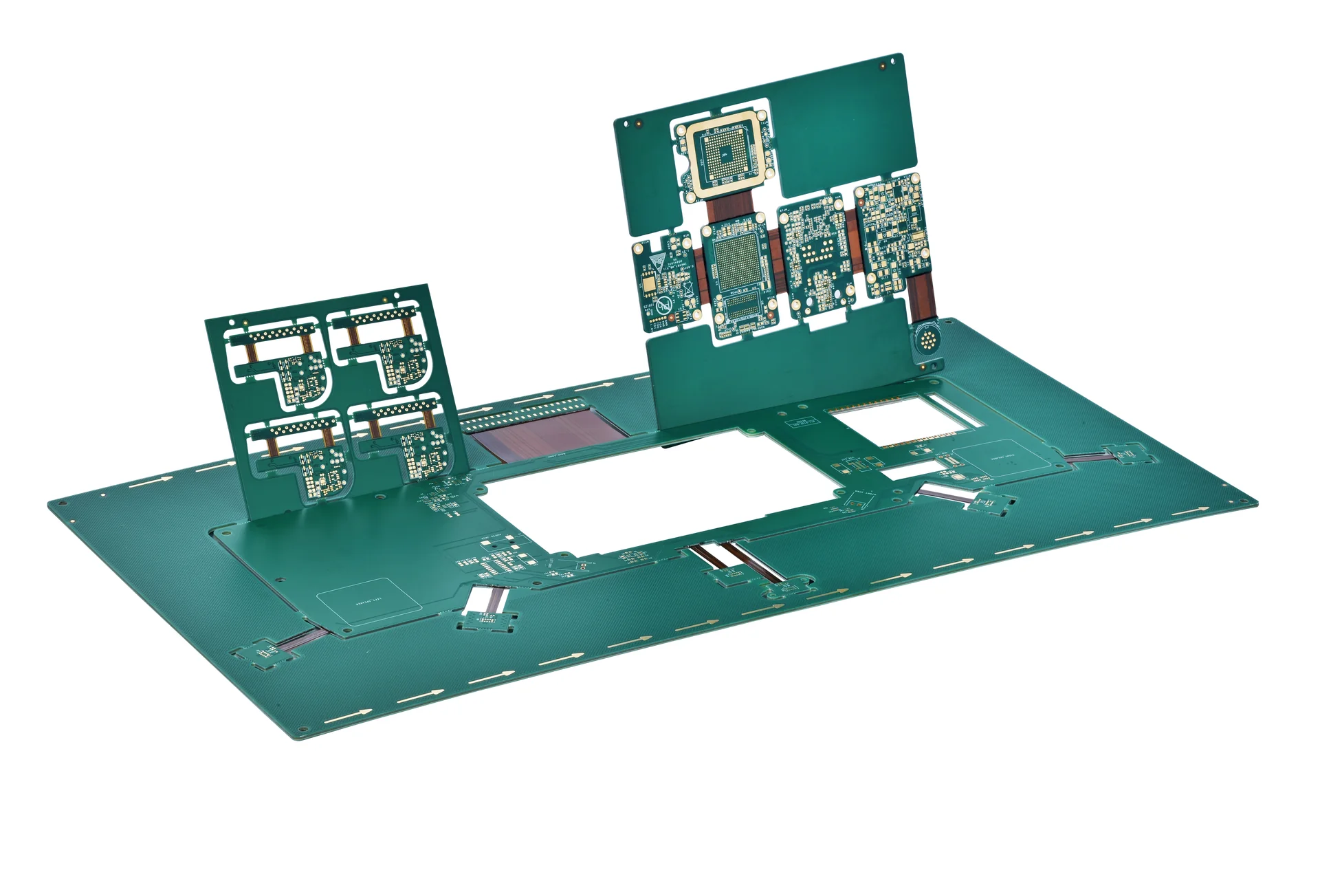
A product photograph shows the arrangement of rigid islands; bend lines and keepouts still require dimensioned drawings.
A note that says keep vias away from the transition is incomplete unless the reference boundary is identified. Show whether the clearance is measured from the finished rigid edge, a material cutback, or another defined feature. Agree the required value and tolerance with the fabricator for the actual stack. Do the same for pads, component outlines, and fastening features that approach the boundary.
The design checker should use the same boundary as the fabrication drawing. A rule applied to a nominal region line can miss a physical edge that moves within its manufacturing tolerance. Review the worst permitted relation between the feature and the controlled edge. This is a geometry check, not permission to invent a new universal clearance.
Coverlay protects the flex conductors, while the rigid region has its own material stack. Their overlap or termination must suit the selected construction. Ask the fabricator how bonding material is controlled near the flex opening and which dimensions it needs to inspect. Do not assume that every visible boundary in a photograph lies on the same internal plane.
Check copper and reference paths across the transition too. A signal can remain continuous while dielectric spacing or its reference structure changes. Keep the electrical requirements connected to the region stackup and review proposed copper changes with the circuit designer. Solving a mechanical issue by removing reference copper can create an electrical problem that a simple clearance check will not find.
Before release, compare the native region definitions, copper and coverlay exports, drill data, flat mechanical drawing, and installed view. Confirm that each file uses the same revision and origin. Include the supplier's approved modifications in that package. A marked-up PDF should not remain the only place where the intended boundary differs from the design database.
IPC identifies IPC-2223 as the flexible printed-board design standard. Refer to the agreed applicable requirements and revision in the project specification. The public listing does not supply a universal transition dimension; the drawing and manufacturing agreement must define the values used for this construction and the method of checking them.
For broader failure mechanisms, the existing rigid-flex interconnection reliability article covers interface and manufacturing considerations. This article's purpose is narrower: to make the physical boundaries, routing constraints, and inspection references unambiguous. Keeping those roles separate lets the design review find a geometry conflict without repeating a full reliability investigation.
The handoff should identify who approves changes to region outlines and who checks the installed form. Mechanical and PCB teams often own different views of the same part, so record their agreement before procurement releases it. Ask the supplier to return unresolved features as a marked drawing rather than a broad statement that the rigid-flex design is acceptable.
For a boundary review, send KnownPCB the rigid-flex region drawing and stackup with the installed shape and required bend areas. Request written confirmation of each critical edge and keepout. The approved detail can then be used by fabrication, assembly, and incoming inspection without reconstructing the intended geometry.
Proven by 7 industries, 4000+ customer projects
Please contact us at sales@knownpcb.com, ask for engineering support here or use the form below to reach out to KnownPCB | Request a Manufacturing QuoteInclude your quantity, target delivery date and key requirements. File handling and NDA information. |