Blog & Design Guide

Specify a flexible PCB bend radius together with the way the circuit moves. A tail bent into position during assembly and a tail moving each time a mechanism operates have different duties. Both can fit inside the same enclosure. That shared space does not make the same construction suitable for both applications.
Start with the installed shape, then examine the path used to get there. During assembly, the operator may temporarily bend the circuit more tightly than it will sit in service. A design reviewed only in its final position can miss that tighter bend, a sharp enclosure edge, or a pull load applied while connecting the tail.
On this page
For flex-to-install use, describe the forming operation and whether the part will be repositioned during service or repair. Static describes its operating duty; it does not mean the circuit experiences no handling. Repeated removal of a connector or opening of a service cover belongs in the mechanical review if it bends the same region again.
For repeated motion, define the travel, bend direction, speed, dwell positions, and required service cycles. Include the temperature range and any tension or torsion imposed by the mechanism. A cycle count without those conditions provides little basis for comparison. The motion fixture should reproduce the part's support and bending path closely enough to test the intended design.
Altium's flex and rigid-flex design discussion separates static ribbons from dynamic ribbons and relates bending to copper and stackup construction. Use that distinction when writing the drawing note. It is more informative than describing every flexible circuit simply as bendable and leaving the manufacturer to infer the intended movement.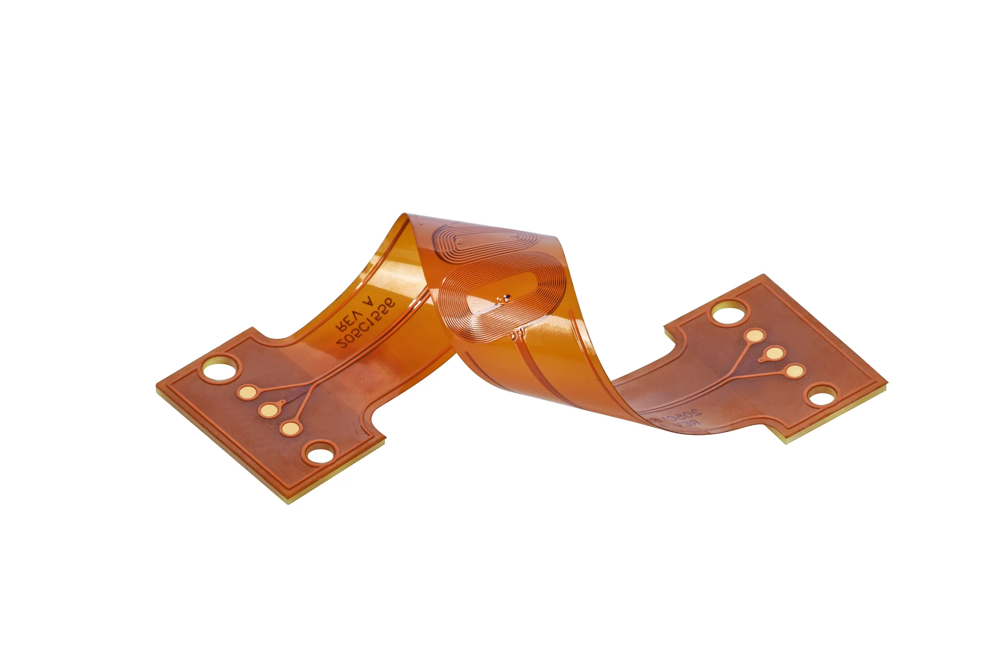
This formed flex illustrates three-dimensional fit; it is not a qualified bend-radius or cycle-life test.
State where the radius is measured. The inside surface, centerline of the flex, and outer surface give different dimensions for the same curved part. Show the reference on a mechanical view and use the same convention in the supplier's review and the validation fixture. Also identify the start and end of the permitted bending region.
Finished flex thickness matters because the copper sits at a distance from the neutral bending region. Increasing that distance increases the deformation imposed on a conductor at a given curvature. A base-film thickness alone omits copper, adhesive, coverlay, shielding, and other layers that can change the finished construction. Obtain a region-specific stackup rather than dividing enclosure space by an incomplete thickness value.
Do not adopt a universal thickness multiplier as an acceptance limit. Published recommendations often assume a particular layer count, construction, and duty. Use them to identify an early packaging conflict, then confirm the design with the fabricator and validate the required motion. This article does not assign a bend-life rating or minimum radius to KnownPCB's whole FPC range.
A narrow tail entering a connector needs controlled contact geometry and enough local support for insertion. The stiffened contact region and the free bending region should appear as distinct areas in the mechanical package. If an operator must pull the free tail to seat the contacts, review access and assembly tooling before asking the circuit to absorb that load.
Place the intended bending region away from abrupt changes in support. A stiffener edge, clamp, bonded patch, or rigid boundary can force the bend into a short length that was not intended to move. Review the complete mounted part. A drawing that shows a generous free span can still result in a tight bend after adhesive or a bracket fixes most of that span in place.
The illustrated flat circuit has a wide functional area and a narrow tail. Its shape helps locate the support and connection regions during a mechanical review. The photograph does not establish the tail's allowable radius, copper type, or service life; those belong in the construction record and agreed test plan.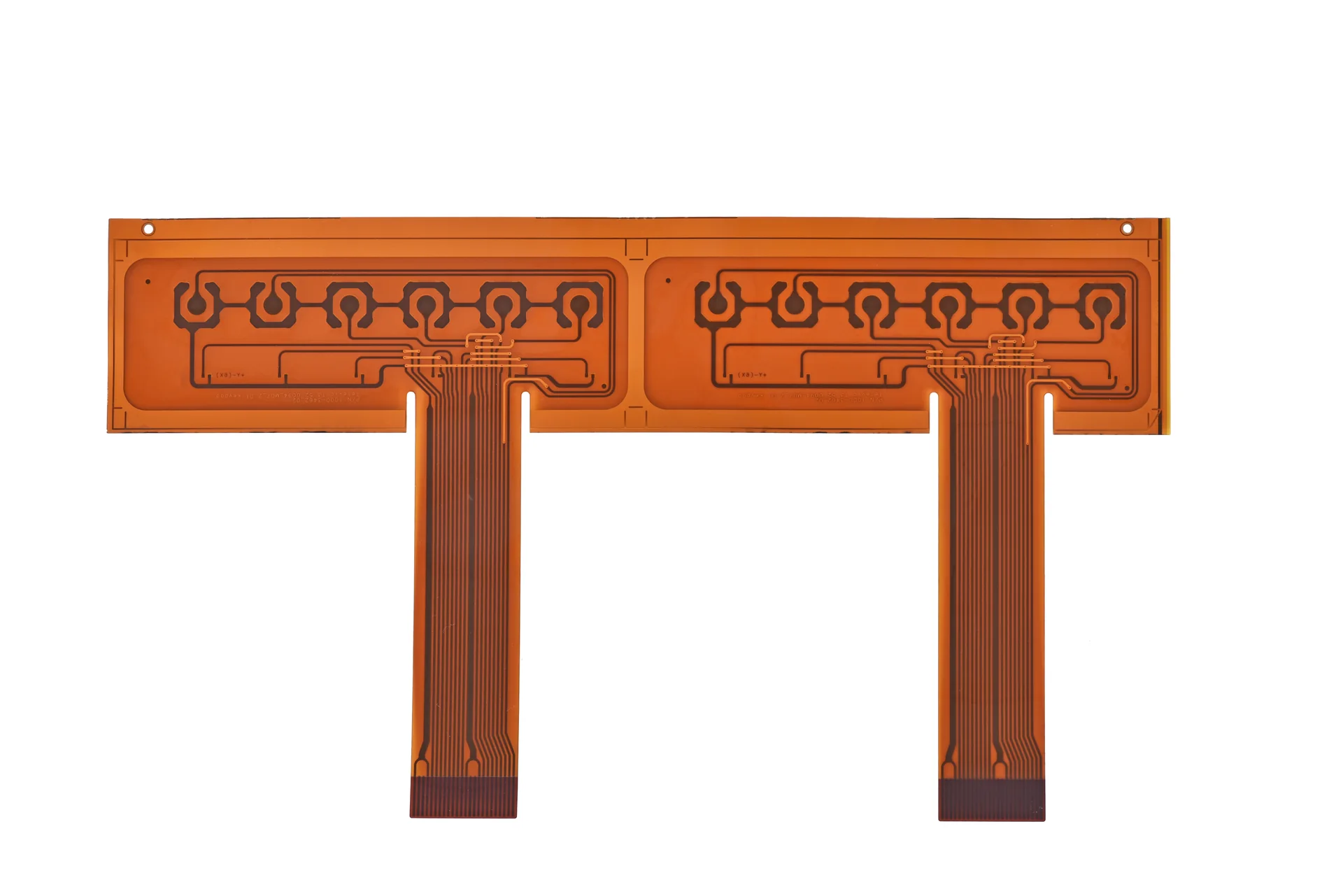
Wide circuit areas and narrow tails can have different support and bending requirements.
A moving cover needs space for the flex to form a controlled loop throughout its travel. Check both end positions and intermediate positions where the loop can touch a housing feature. Avoid relying on a single folded CAD view. A loop that looks clear at rest can rub an edge or develop twist halfway through the movement.
Routing should suit that movement. Keep pads and plated holes outside the active bending region where possible, and avoid abrupt conductor changes there. Copper distribution on opposite layers affects local stiffness. Any proposal to change a reference plane or use a hatch pattern must also be checked electrically; mechanical flexibility does not remove signal-return requirements.
Record the laminate system, copper construction, coverlay, and any shielding or bonding layers in the test sample. Samples should represent the finished active region. A bare piece of base film or an unpopulated tail with missing protective layers cannot automatically establish the behavior of the assembled product. Assembly thermal exposure should be considered where it changes the qualification conditions.
Agree how failures are detected. A visual check can find a tear or crease but may miss an intermittent conductor that opens only during movement. Depending on the application, validation may need continuity monitoring through the travel and a defined rule for resistance change. Specify the measurement arrangement and acceptance criteria before running the test rather than interpreting an unexplained pass afterward.
IPC lists IPC-2223 as the sectional design standard for flexible printed boards. Use the applicable agreed standard together with the design's mechanical requirements. A standards reference alone does not define your enclosure, motion, supports, or required life. Those application details still have to be communicated and checked.
KnownPCB's flexible PCB manufacturing page is the product entry point for FPC projects. For a bend review, provide the flat artwork, region stackup, installed shape, radius datum, and motion description together. Add the fixture or housing model when contact with the enclosure determines the bending path.
Keep connector handling separate from the bend calculation. The existing FPC assembly-detail article discusses insertion and handling problems. A circuit can satisfy an agreed bend geometry and still be damaged by reverse insertion, pulling, or poor access during installation. Both reviews should use the same finished design revision.
Before release, request an FPC construction review that names the intended duty and unresolved packaging constraints. The result should be an approved geometry and validation plan for this circuit, with any assumptions written down. It gives assembly, procurement, and quality teams the same bending requirement to preserve.
Proven by 7 industries, 4000+ customer projects
Please contact us at sales@knownpcb.com, ask for engineering support here or use the form below to reach out to KnownPCB | Request a Manufacturing QuoteInclude your quantity, target delivery date and key requirements. File handling and NDA information. |