
A PCB TDR impedance test should leave enough information for another engineer to understand what was measured. A report containing one green pass box and an impedance value cannot explain the coupon, the measurement window or the link to the delivered production lot. Those details decide how useful the result will be when a board is reviewed or repeated.
Read a production report from the sample identity outward. Confirm the part revision and coupon first, then inspect the acquisition conditions and the calculation. This order catches a common documentation failure: a believable result attached to the wrong structure.
Read the report in this order
Look for the PCB part number, artwork revision, production lot and coupon identifier. Then find the controlled structure: single-ended or differential, signal layer, reference plane and target impedance. The stackup revision should connect the measurement to the construction approved for that lot.
A coupon is a test structure fabricated with the panel. Its line geometry and layer environment should represent the controlled structure being accepted. Check whether outer-layer solder mask, adjacent copper and the relevant reference plane are represented. A convenient line on the panel border is useful only if its relationship to the production trace is understood.
Sampling must also be visible. One measured coupon, several panel positions and every production panel are different inspection scopes. Agree the scope before production, then identify what the delivered report covers. A buyer should not have to infer panel sampling from the number of waveform images in a PDF.
KnownPCB's controlled-impedance manufacturing article explains how design, process control and verification relate. A TDR report is the measurement record within that system. It should preserve the connection between the approved structure and the sampled production result.
Time domain reflectometry sends a fast transition into the structure and observes the returning response. Reflections contain information about impedance changes along the connected path. The probe launch, the useful line section and the far end all contribute to the displayed waveform, so the report needs to identify which part is used for acceptance.
The IPC method IPC-TM-650 2.5.5.7 Revision A covers characteristic-impedance measurement by TDR and explains limitations from the sample and measurement system. Use the contractually agreed method and revision. The linked document is a specific published revision, rather than a claim that every test must use that edition.
A window set too near the launch can include probe settling. A window near the far end can include the termination response. The line must leave enough usable time between these effects for the selected method. Changing the window can change the reported value, even though nobody touched the coupon.
Keep the waveform with its axes and window markers. Report the statistic used for acceptance, such as the agreed average over the selected region, and how excursions are handled. Do not silently substitute a cursor value at one attractive point for a measurement defined across a region.
The instrument close-up below illustrates a displayed impedance waveform and cursor region. The photograph is an equipment example and is not a report for the hypothetical conditions discussed here.
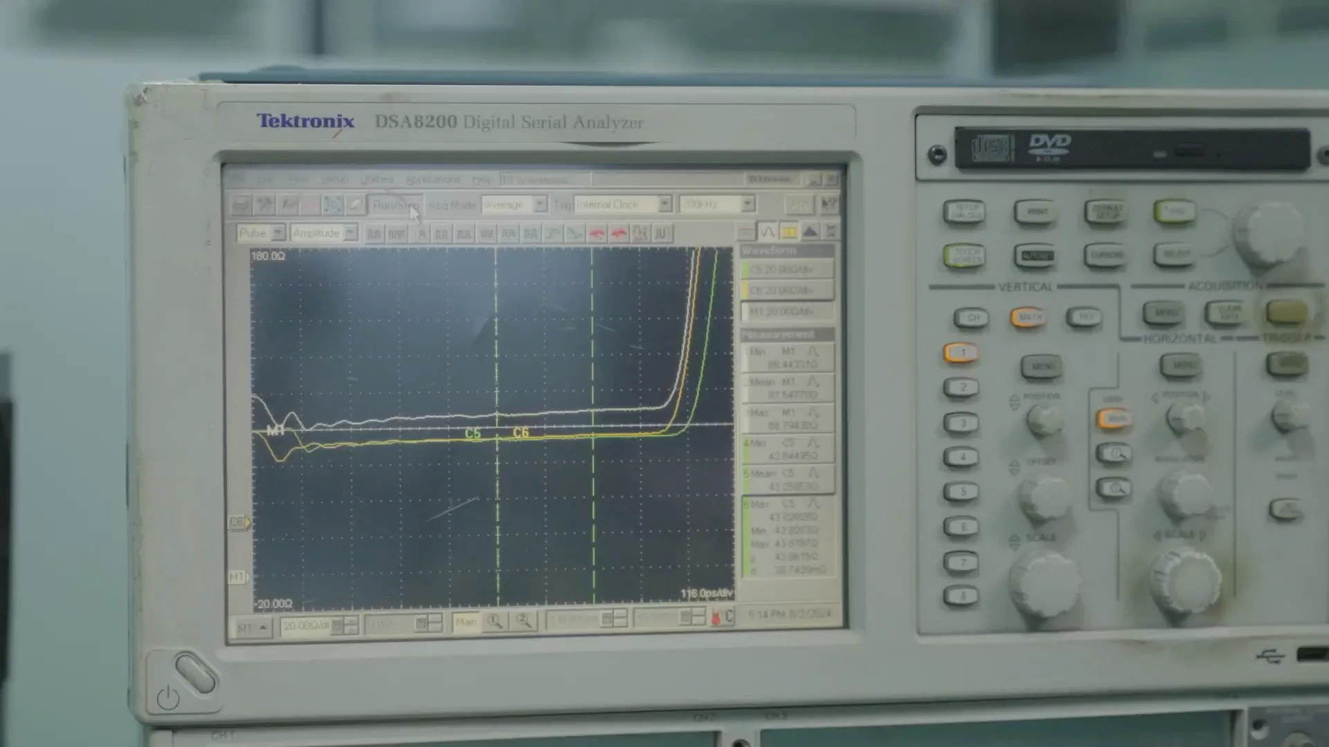
The instrument display illustrates waveform review; no lot acceptance result is inferred from this photograph.
Rise time affects the detail visible in the response. A setup that resolves a uniform coupon adequately may not separate two closely spaced discontinuities. Record the effective rise time or bandwidth conditions relevant to the agreed method, together with instrument and probe identification. Report any filtering, deskew or fixture correction that materially changes interpretation.
Tektronix's TDR measurement primer explains reflected responses and the effect of measurement conditions. This background is useful when reviewing a trace, but the production acceptance rule still belongs in the purchase and inspection agreement.
Consider an illustrative requirement of 50 Ω with an agreed tolerance of ±10%. The numerical limits would be 45–55 Ω. This arithmetic defines an example window; it does not establish a suitable tolerance for your interface or a blanket factory capability.
Now consider two reports reading 49.8 Ω and 51.2 Ω. Before calling that manufacturing drift, compare coupon revision, layer, mask condition, instrument settings and analysis window. If the method changed between the two lots, the difference may include measurement variation as well as board variation. Save the earlier setup with the earlier result so the comparison can be repeated.
For a differential structure, confirm that the report states differential impedance and the associated connection method. A single-ended result from one line cannot simply be relabeled as a differential acceptance result. Pair geometry, coupling and the measurement arrangement need to match the definition used in the specification.
If a reading fails, first confirm sample identity and setup. Repeat according to the established procedure, keeping the original result in the record. If the failure remains, connect it to physical evidence such as finished trace geometry or dielectric spacing. Repeatedly shifting the window until a result passes destroys the usefulness of the inspection record.
The bench image below shows an operator using impedance test equipment. It provides testing context without identifying a particular coupon, lot or sampling plan.
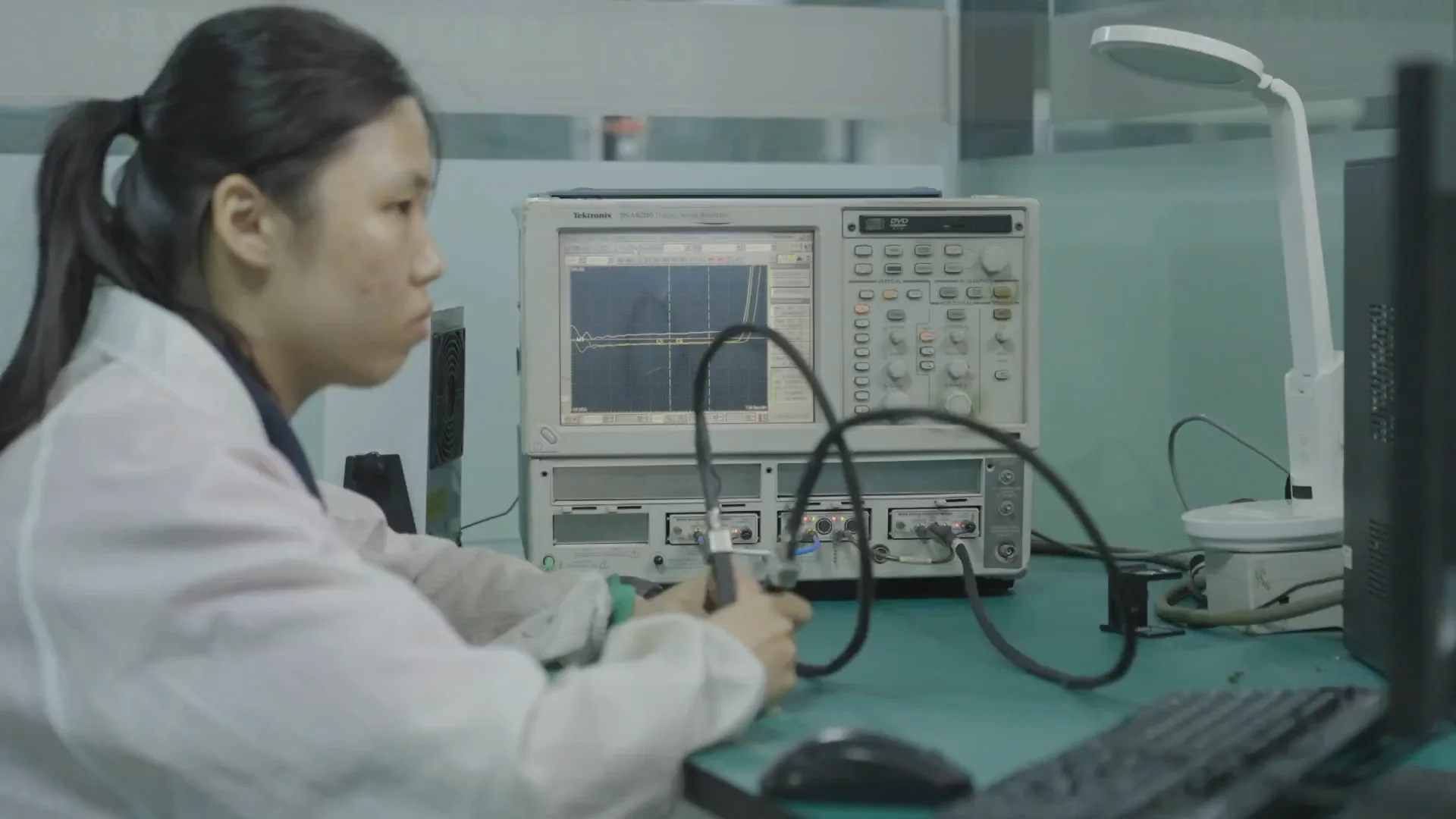
The testing bench provides process context; coupon identity and sampling belong in the measurement record.
For procurement, the most useful request is a defined deliverable rather than “include impedance testing.” Specify the controlled structures and targets, the representative coupons, sampling scope, method and the required report fields. Include whether waveform files or only the reviewed report are required, and resolve that distinction before quoting.
TDR coupon acceptance does not by itself establish channel insertion loss, protocol compliance or the behavior of every transition on the assembled product. If the product needs frequency-domain or system verification, define that work separately so nobody assumes it is included in a bare-board report.
KnownPCB's quality-management information is the starting point for discussing inspection records. Submit the impedance table and requested report scope with your fabrication data so the quotation can identify the measurement deliverable clearly.
October/08/2026Single-Sided vs. Double-Sided PCB: Routing and Cost

April/24/2026Aluminum vs Copper vs Stainless Steel MCPCBs: Thermal Performance, Cost and Applications
September/28/2026PCB Plating Voids in Through Holes: Causes, Evidence and Prevention
June/24/2026High-current Heavy Copper PCB
October/06/2026PCB Desmear Process: Resin Smear Removal Before Plating
